

![]() Wed May 13, 2015 7:58 pm
Wed May 13, 2015 7:58 pm
Antique S&G C-71 or 6700 safe lock (pic heavy)
Hold on Olfast, you need to pace yourself or you might have a stroke.  If you want to see any pictures large just click on it and then there should be a little magnifying glass to zoom in. If not just click the picture again.
So in 1927 S&G changed their C-71 safe lock into the 67XX designation. Since this one has a square bolt it is a 6700. Different types of end bolt make it a 6701, 6702 etc. Mine is a little different than the one pictured in the catalog so I believe it is an earlier version.
Unfortunately sometime in this locks life it was drilled so I do not believe it is the original dial but it is the original dial ring since it is number matching. You will see why this is important in a little bit.. HOLD ON OLDFAST! You scroll that fast you are going to catch your mouse on fire.
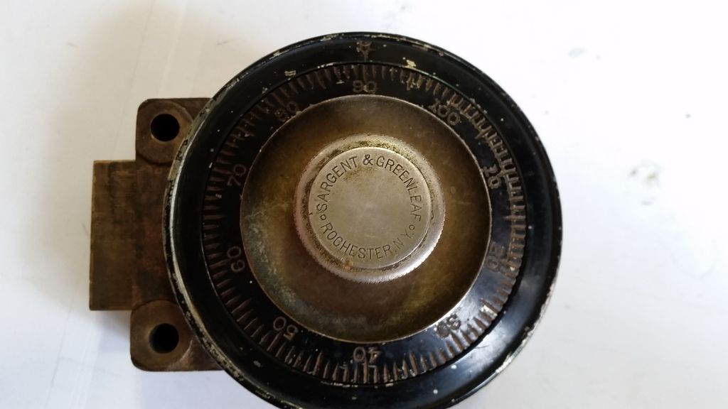
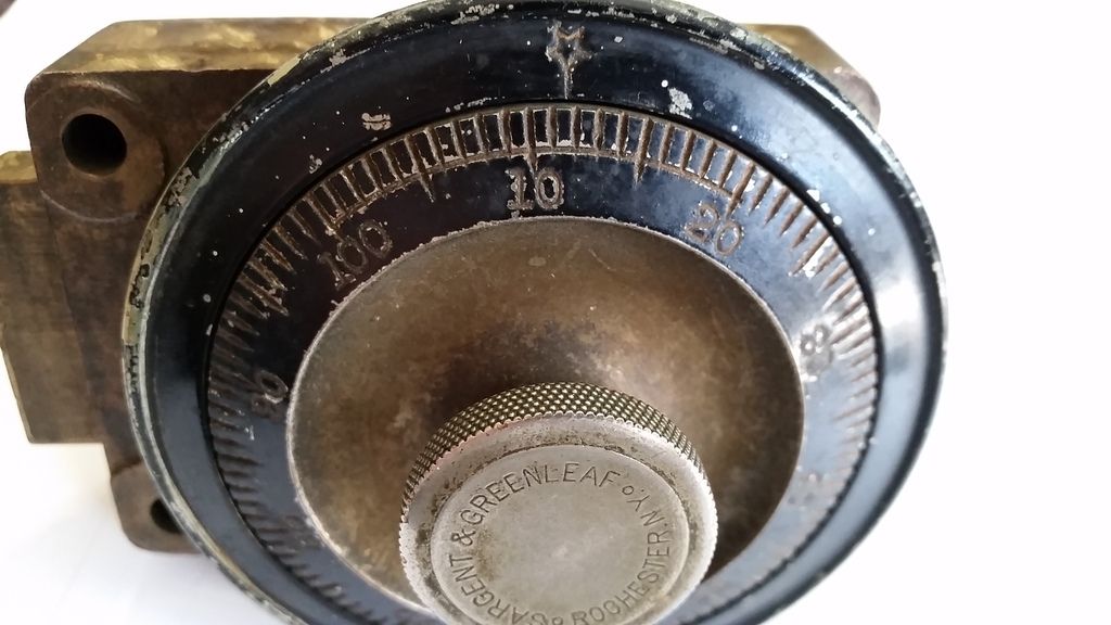
The lock and a close up of the dial. This one has a second line through the 100-20 to mark the forbidden zone instead of just leaving those numbers out. I haven't seen one like that before.
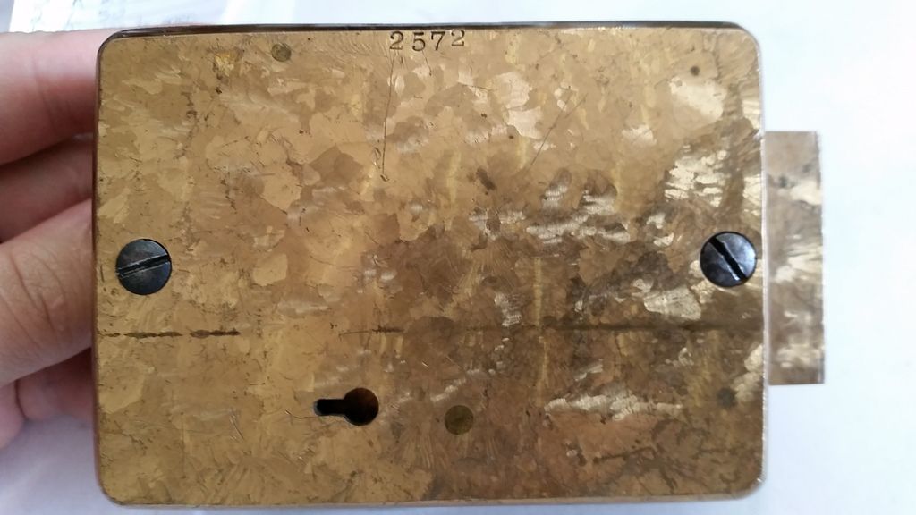
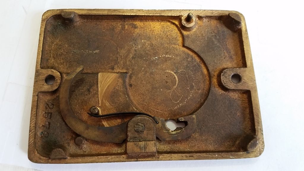
Here you have the back of the case. It is made of bronze and I believe it is called a scalloped or scallop shell finish.
The inside of the cover. The odd lever interacts with the lever in the safe lock when you are changing the combination. It lifts it up so that the nose of the lever does not fall into the drive cam. When you turn the change it it lifts up.
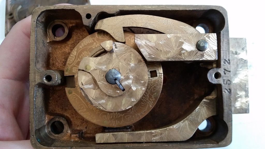
And the inside of the lock. Everything you can see is nicely patterned. If you follow the lever to the right, just below the left side of the rivet you can see a little nub sticking out. This is what the lever on the back of the cover pushes against to hold it up.
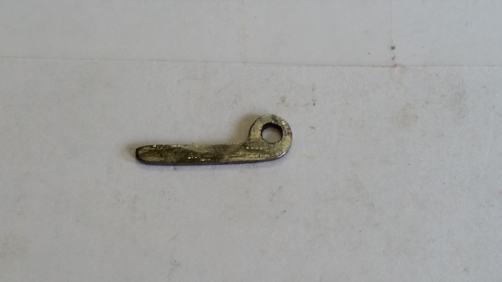
The spline key. These old ones are nice since you can just use a hook to pull them out.
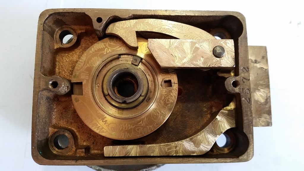
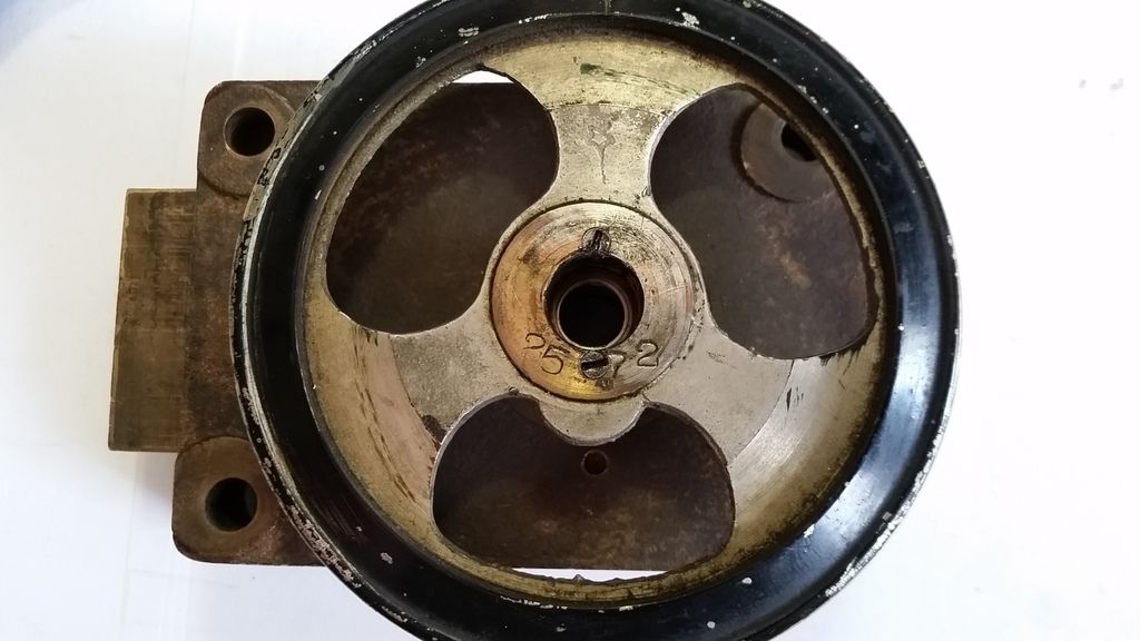
Now take off the drive cam and the dial.
What the hey?! The dial ring is stuck! If you look closely to at the middle you will see 2 small screws. These had me confused at first. I thought the only thing holding the dial ring on was the dial being right.
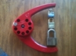
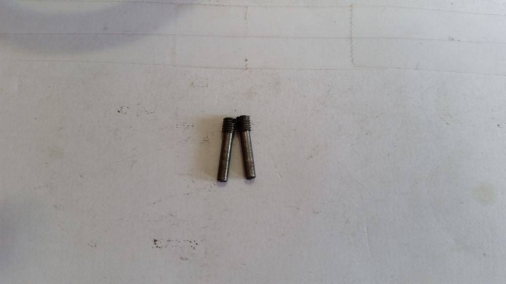
Take those screws out and they are pins.
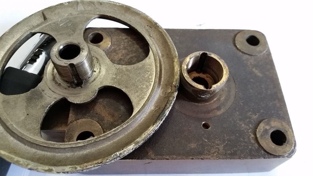
Pull the dial ring off...... nope, unscrew the dial ring. You can see that it is threaded to allow for adjustment of length for the spindle. The reason it was done this way is because it was labeled for Fire Proof applications as you will see in the catalog page I will show. With this one you have minimum 1/2" up to almost 1" of adjustment. The pins index to prevent the dial ring from rotating and they are offset so that you can only put them in with the ring in the correct upright position.
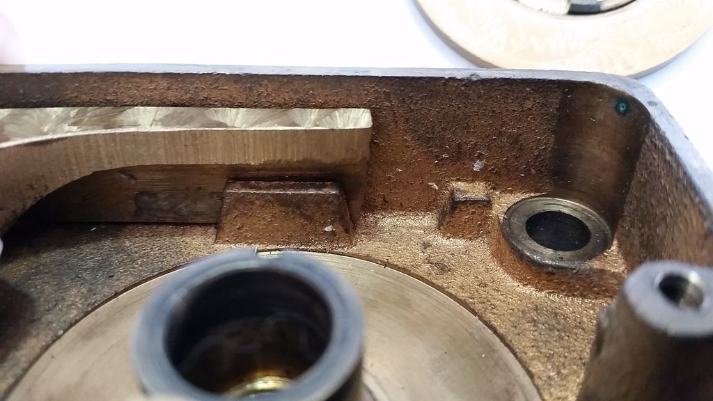
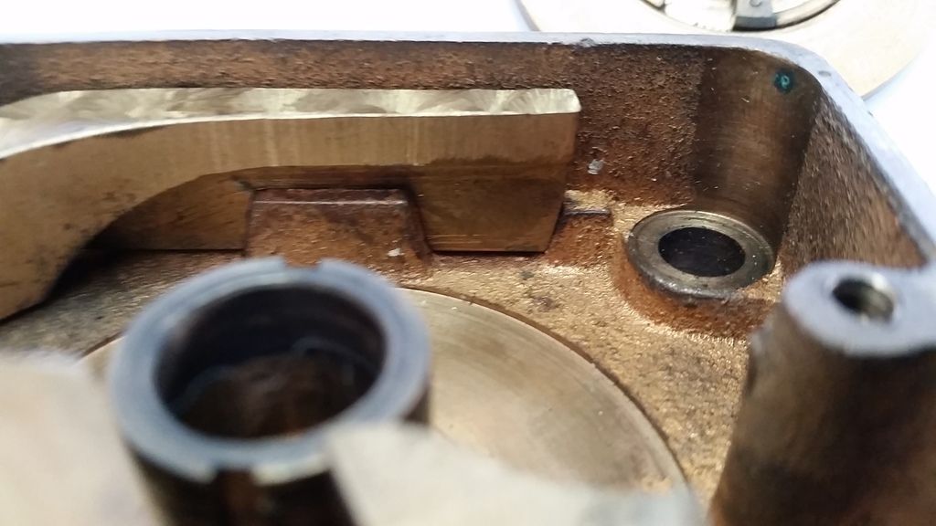
One neat thing is the bolt stop. It is on the bottom of the bolt/lever assembly. This prevents damage to the fence/lever from hitting the inside of the case.
Here it is when in the locked position
And the unlocked position
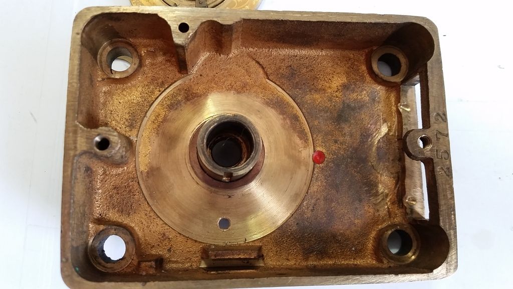
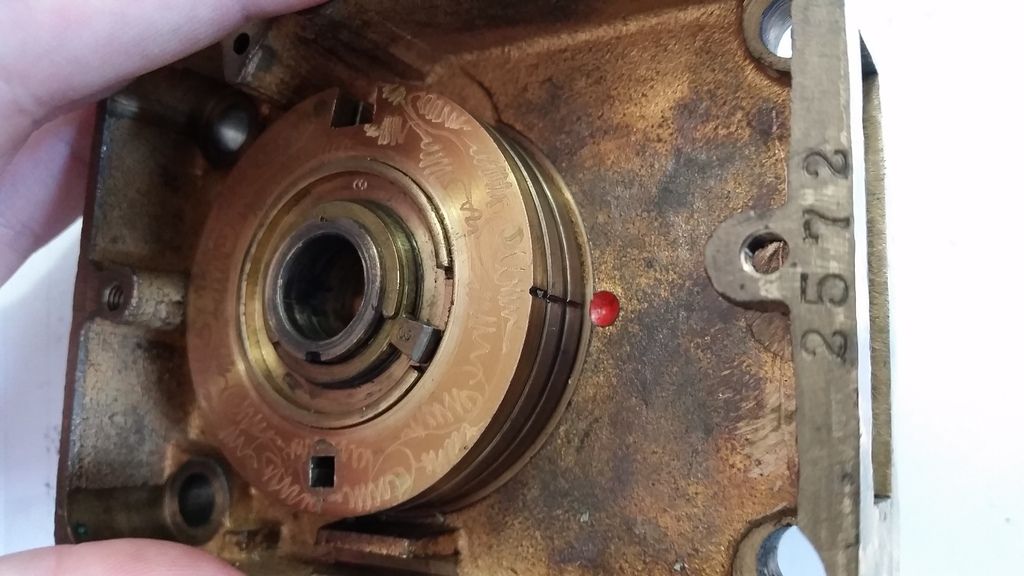
Here is the fully gutted case. You can see the hole where it was drilled to find the gates. Notice the red dot? More on that later
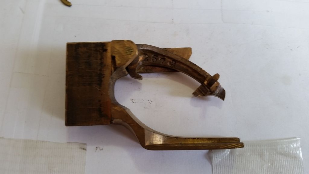
The back of the bolt/lever assembly. On the bottom of the lever you can see where the lever on the back of the cover pushes against to keep it up.
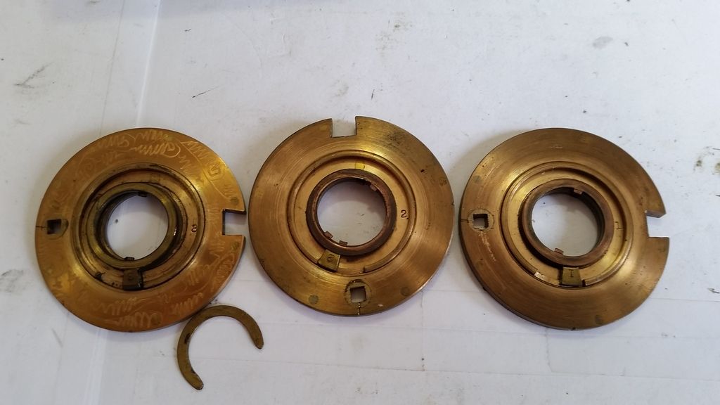
The wheels. You can see that the one on the left is engraved while the ones that sit below it are not. Each has its pieces numbered as well.
Now on to the little red dot. Catch the red dot Xeo! There are lines on the sides of each wheel. When those are lined up with the dot each wheel has its gate lined up with the fence. This makes it nice since it can be hard to see, especialyl if it is mounted in a safe.
And finally, the catalog page from 1927. All of the measurements line up but the fence/bolt is a little different.
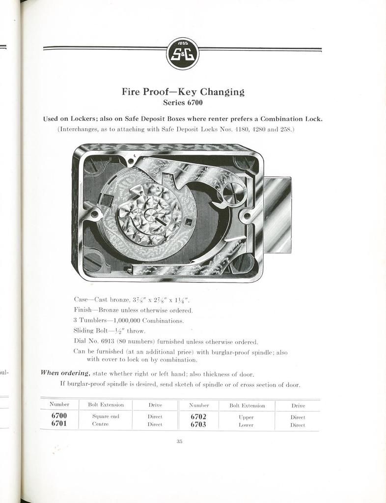
So in 1927 S&G changed their C-71 safe lock into the 67XX designation. Since this one has a square bolt it is a 6700. Different types of end bolt make it a 6701, 6702 etc. Mine is a little different than the one pictured in the catalog so I believe it is an earlier version.
Unfortunately sometime in this locks life it was drilled so I do not believe it is the original dial but it is the original dial ring since it is number matching. You will see why this is important in a little bit.. HOLD ON OLDFAST! You scroll that fast you are going to catch your mouse on fire.
The lock and a close up of the dial. This one has a second line through the 100-20 to mark the forbidden zone instead of just leaving those numbers out. I haven't seen one like that before.


Here you have the back of the case. It is made of bronze and I believe it is called a scalloped or scallop shell finish.

The inside of the cover. The odd lever interacts with the lever in the safe lock when you are changing the combination. It lifts it up so that the nose of the lever does not fall into the drive cam. When you turn the change it it lifts up.

And the inside of the lock. Everything you can see is nicely patterned. If you follow the lever to the right, just below the left side of the rivet you can see a little nub sticking out. This is what the lever on the back of the cover pushes against to hold it up.

The spline key. These old ones are nice since you can just use a hook to pull them out.

Now take off the drive cam and the dial.

What the hey?! The dial ring is stuck! If you look closely to at the middle you will see 2 small screws. These had me confused at first. I thought the only thing holding the dial ring on was the dial being right.

Take those screws out and they are pins.

Pull the dial ring off...... nope, unscrew the dial ring.

One neat thing is the bolt stop. It is on the bottom of the bolt/lever assembly. This prevents damage to the fence/lever from hitting the inside of the case.
Here it is when in the locked position

And the unlocked position

Here is the fully gutted case. You can see the hole where it was drilled to find the gates. Notice the red dot? More on that later

The back of the bolt/lever assembly. On the bottom of the lever you can see where the lever on the back of the cover pushes against to keep it up.

The wheels. You can see that the one on the left is engraved while the ones that sit below it are not. Each has its pieces numbered as well.

Now on to the little red dot. Catch the red dot Xeo!

And finally, the catalog page from 1927. All of the measurements line up but the fence/bolt is a little different.

PhoneMan: I always knew I'd say something stupid and it would be someone's sig
macgng: i am an equal opportunity pervert
macgng: aww fuck thats goin in someone sig :-(
If life gives you melons, you might be dyslexic.
macgng: i am an equal opportunity pervert
macgng: aww fuck thats goin in someone sig :-(
If life gives you melons, you might be dyslexic.