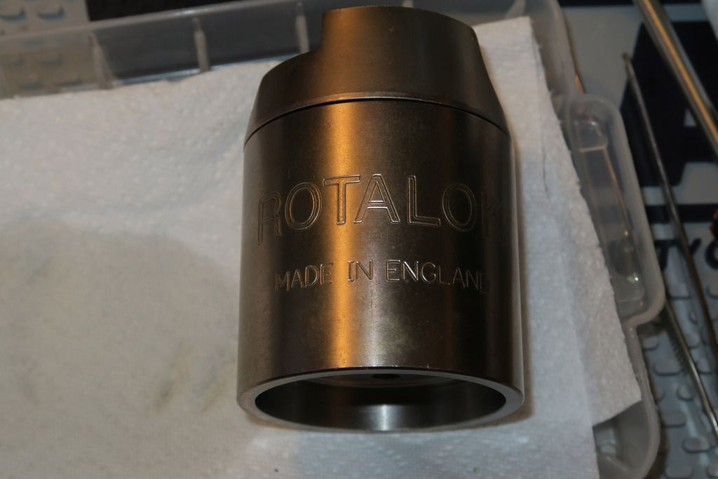
The following is (yawn, I know) ANOTHER Rotalok post. However, this is a Rotalok post with a difference – it’s an entirely new lock. I didn’t especially plan on this purchase but when I saw it pop up on eBay, considering how unusual it is, I *had* to have it. Why, you may ask? Well, what Rotalok cores have we seen so far? Abus E60, Cisa Astral and Assa Twin Combi. And we’ve fitted the Rotas with an EVVA MCS, an EVVA 3KS and also another random Evva that I had. And what do those cores have in common? Well, they are all “slot” shape keys that utilise the same keyway cutout pattern on the Rotalok – that kinda Z shape that allows rotation of an oblong key. So imagine my surprise when I saw this pop up on eBay:
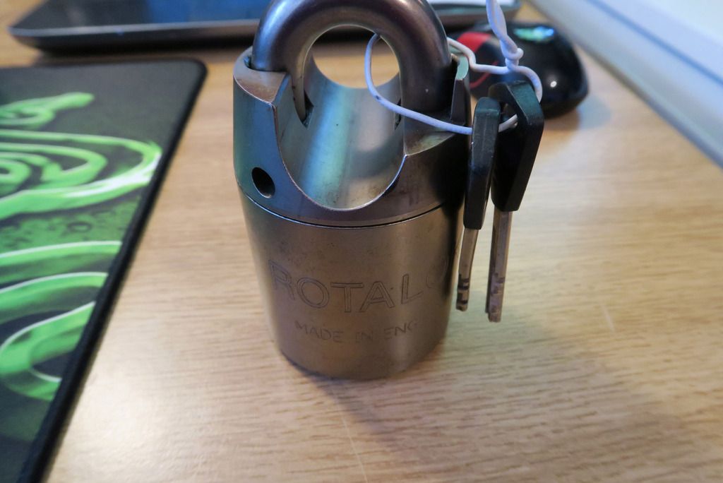
Is... Is that what I think it is?
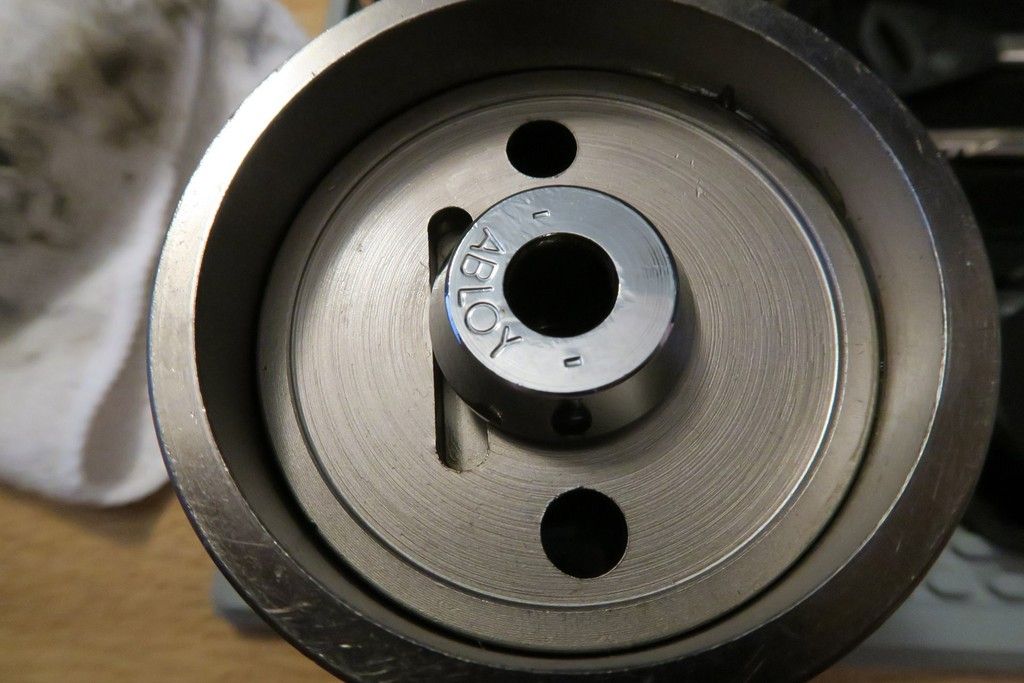
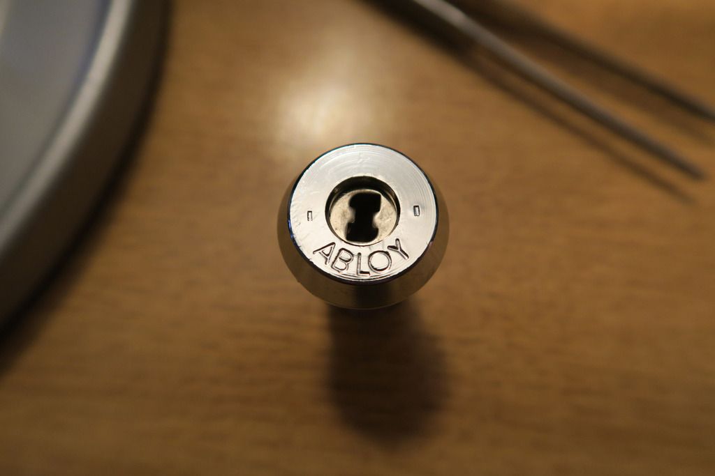
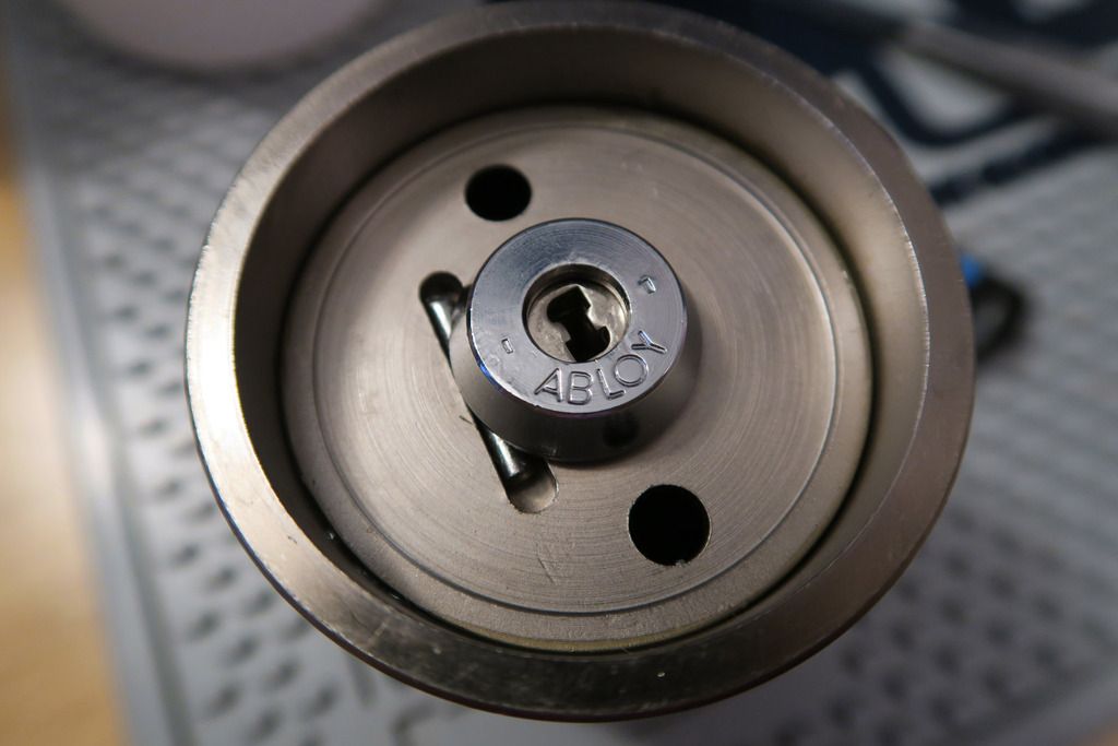
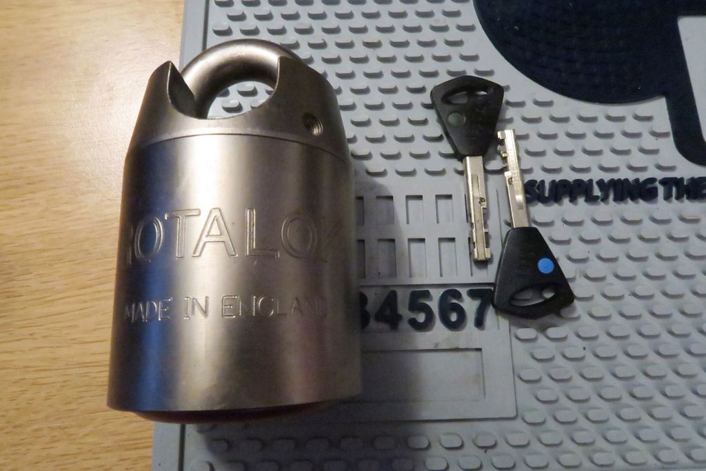
Oh boy! It’s an Abloy cylinder – but not only that, it’s an Abloy Exec (as far as I can tell, based on the key bow shape and distinguishing features on the key). You don’t see those around very much – mostly either the Classic/Profile/High Profile on the “old” end, or Sentry/Protec/Protec 2 on the “new” etc. So that would be reason enough to pay attention to this lock. But that’s not the only surprise in store...
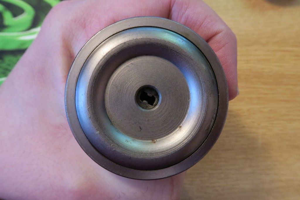
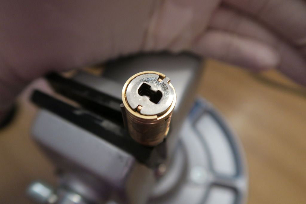
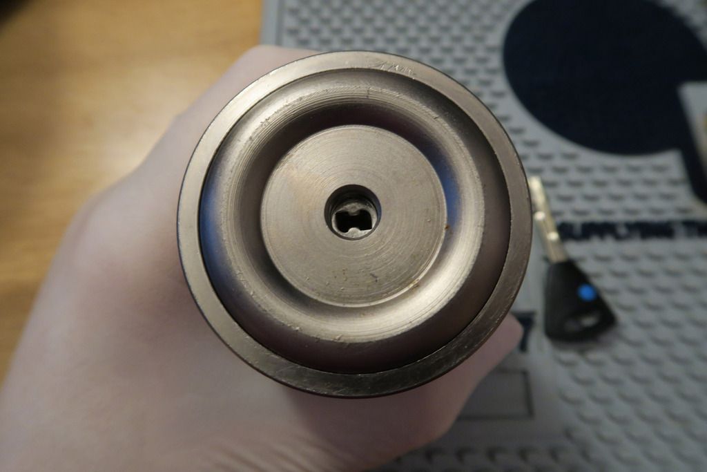
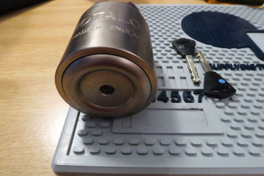
Holy moly! A perfectly round keyway cutout on the bottom plate, shaped for central-access cores like the Abloy, Anchor Las and DOM Diamant ranges. This is the first time I’ve ever seen this kind of bottom plate (and it took a careful eye to notice it on the auction listing) so I dunno if this is a special order for some company or government, or just a variation that is rarely seen, but yeah... Wow! So, does this use an Abloy ½ Euro cylinder? Well, let’s crack it open and find out! Not literally of course.. All I’d achieve is to break my hammer

.
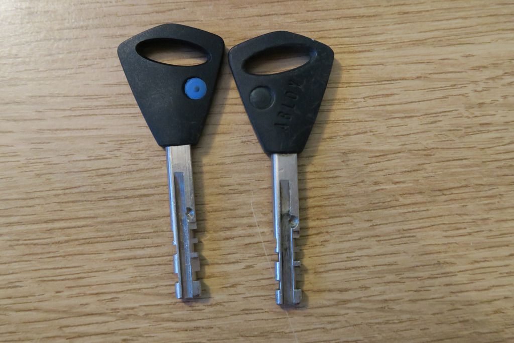
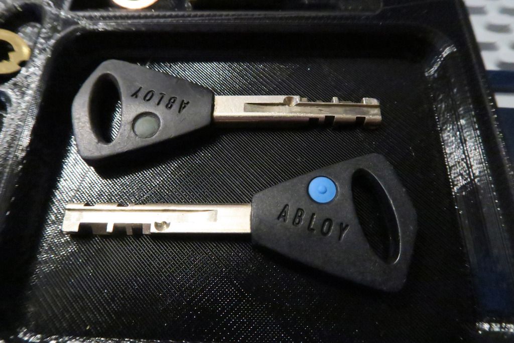
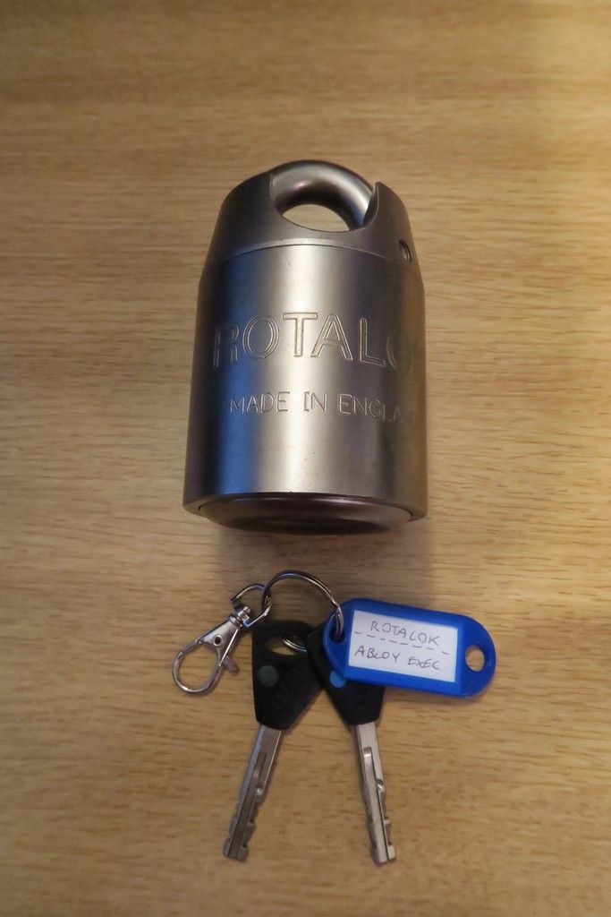
Let’s start with another look at the keys:
I’m of the belief that the black plastic handles with the slanted oval cutout shape (where the keyring goes) signifies that these are Abloy Exec keys. I believe that these are a direct successor to the High Profile range, and preceded the modern era Protec/Sentry keys (though I’m of conflicting info about the exact dates for the production of these as well as the Disklock range since different sources say different things) but I do know the Exec system is “one-way” and was designed as a replacement for the High Profile specifically for applications such as padlocks, cam locks and furniture locks. Exec can use 11 (standard) or 9 (short) disks, and uses a “Disk Steering System” to ensure that the key is fully inserted before it’s allowed to turn – I’ll explain this in further details when we get to the relevant photos

.
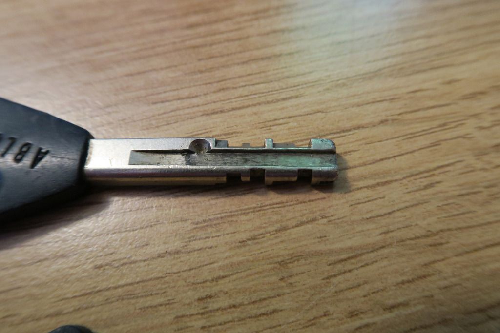
In this close-up, you can see the slanted-cut bitting that is ubiquitous in Abloy locks, as well as a single dimple cut – this is for the aforementioned Disk Steering System (Hereafter referred to as DSS).
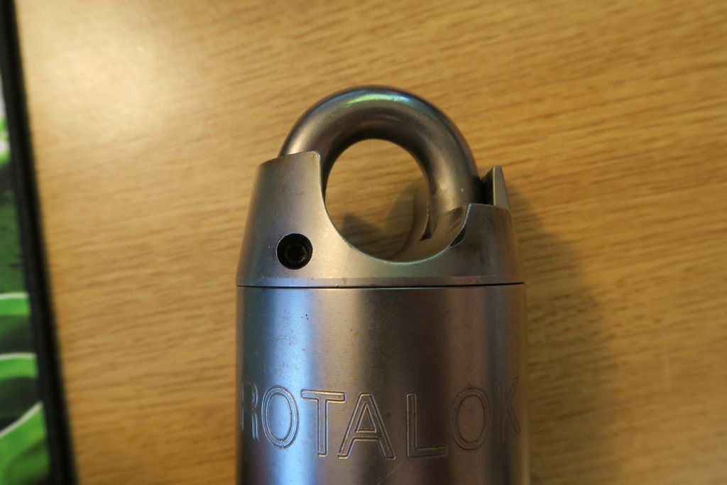
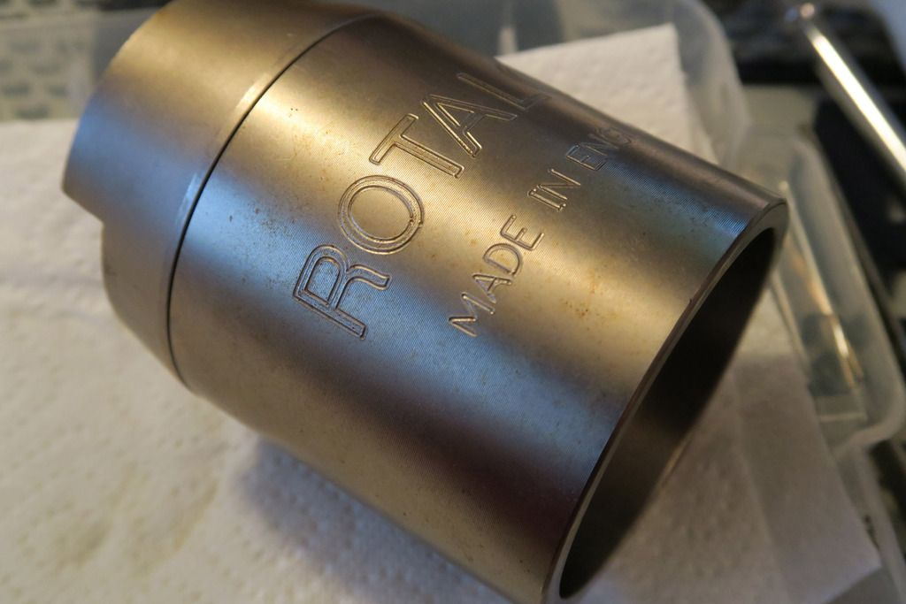
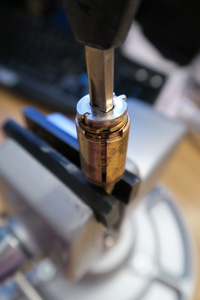
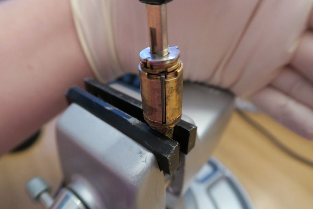
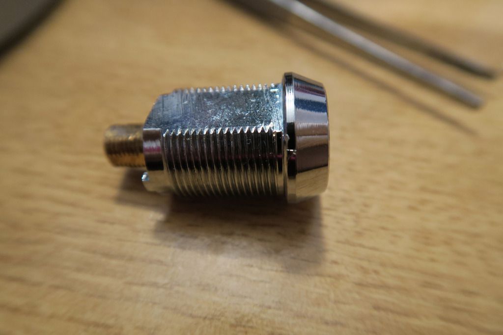
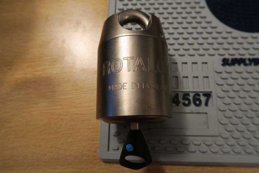
The majority of the body of this Rotalok is just like my other all-silver-body semi-closed Rota:
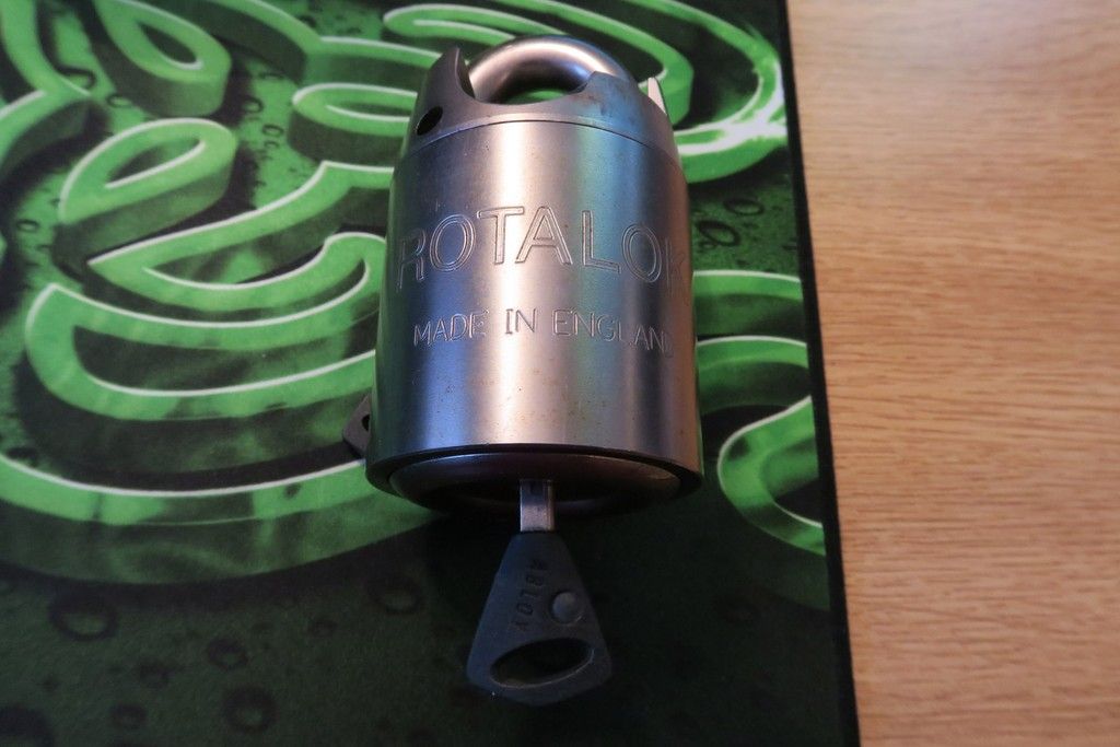
And it’s the exact same operation to open:
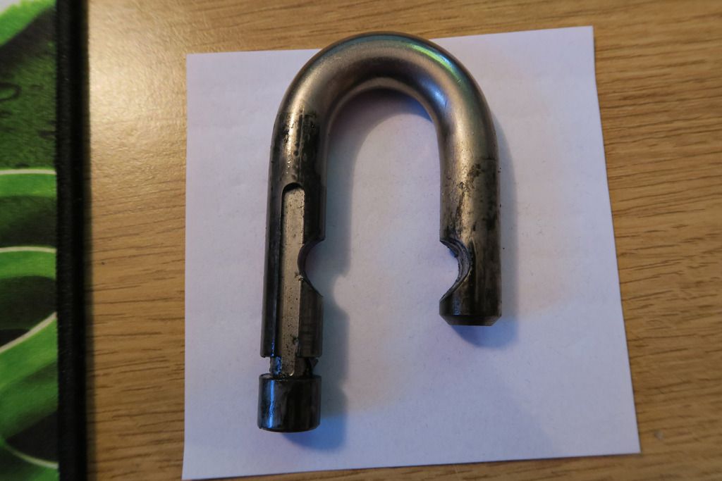
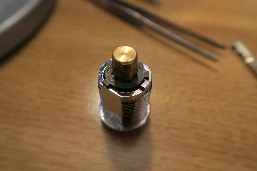
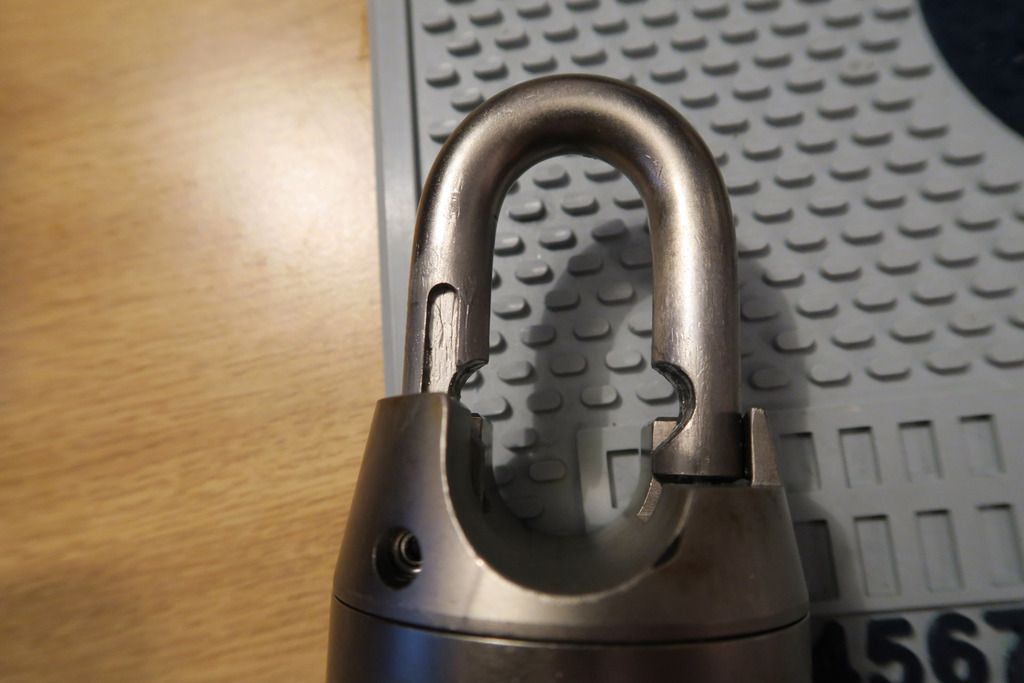
This particular lock uses a different method for shackle retention though – at this point in taking the photos the shackle came all the way out and I thought that the shackle retaining bar was missing, but in face I’d already loosened its retention screw, and we’ll get to that in a bit:
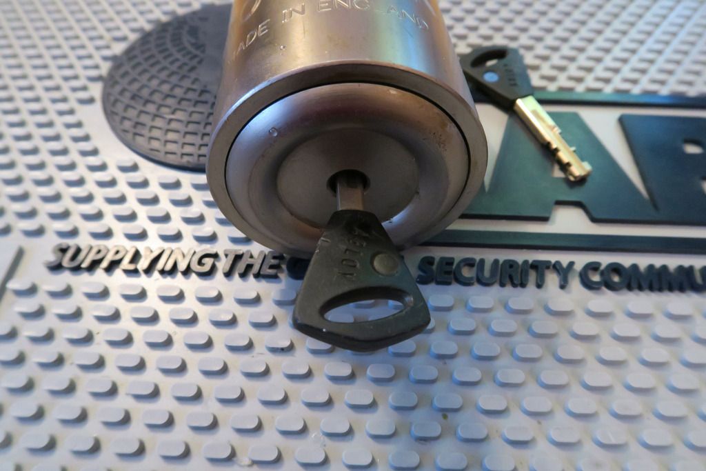
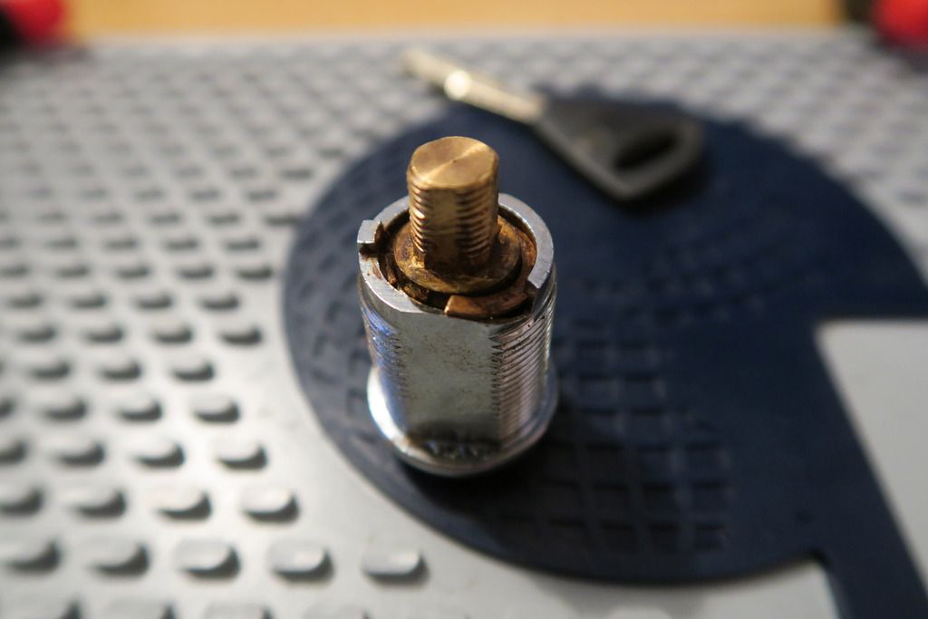
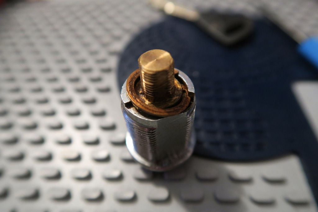
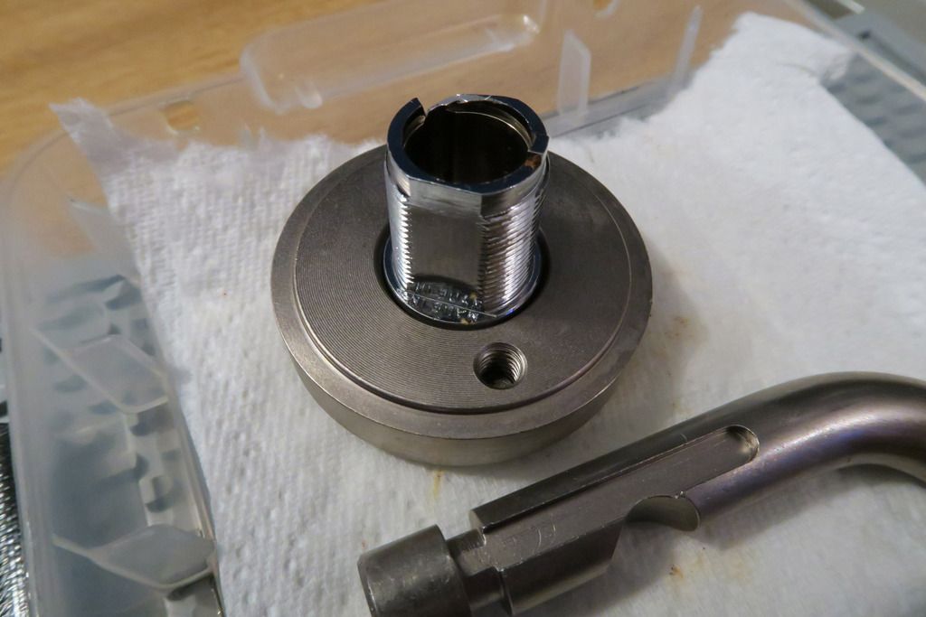
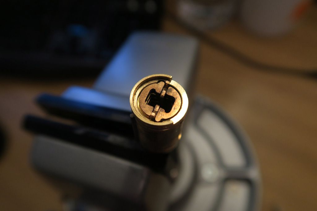
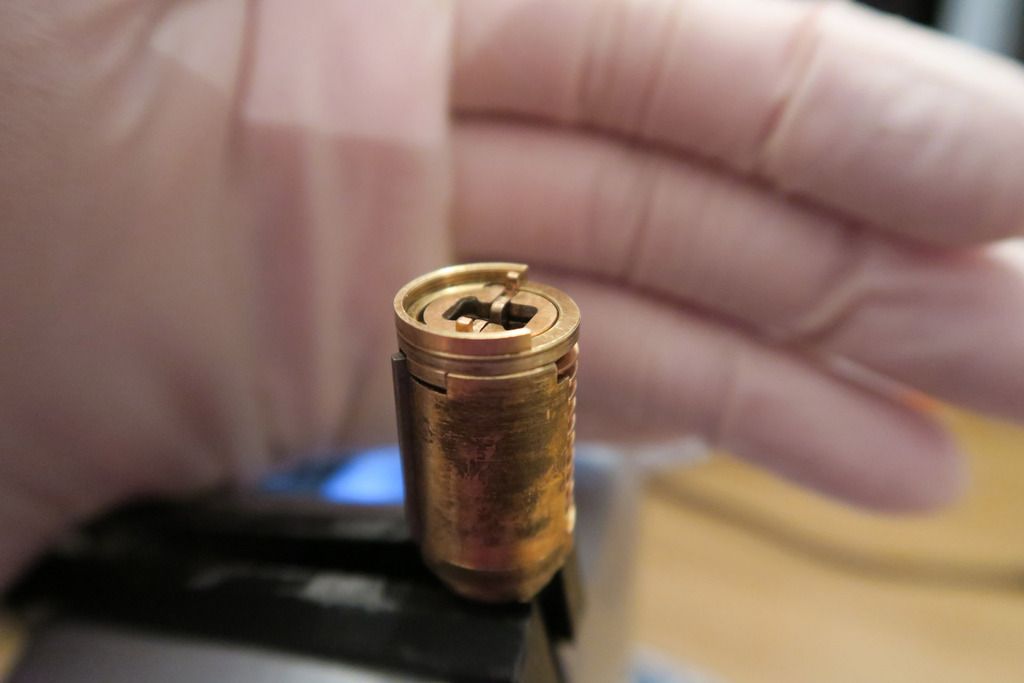
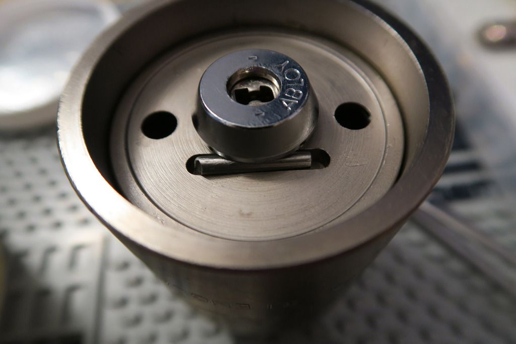
Top of the lock – it’s a bit rusty:
Showing the key in the body. Love that central-hole bottom plate:
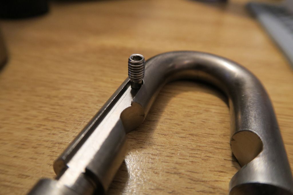
This is the screw that came out of the shackle retention hole – where I thought the bar would go:
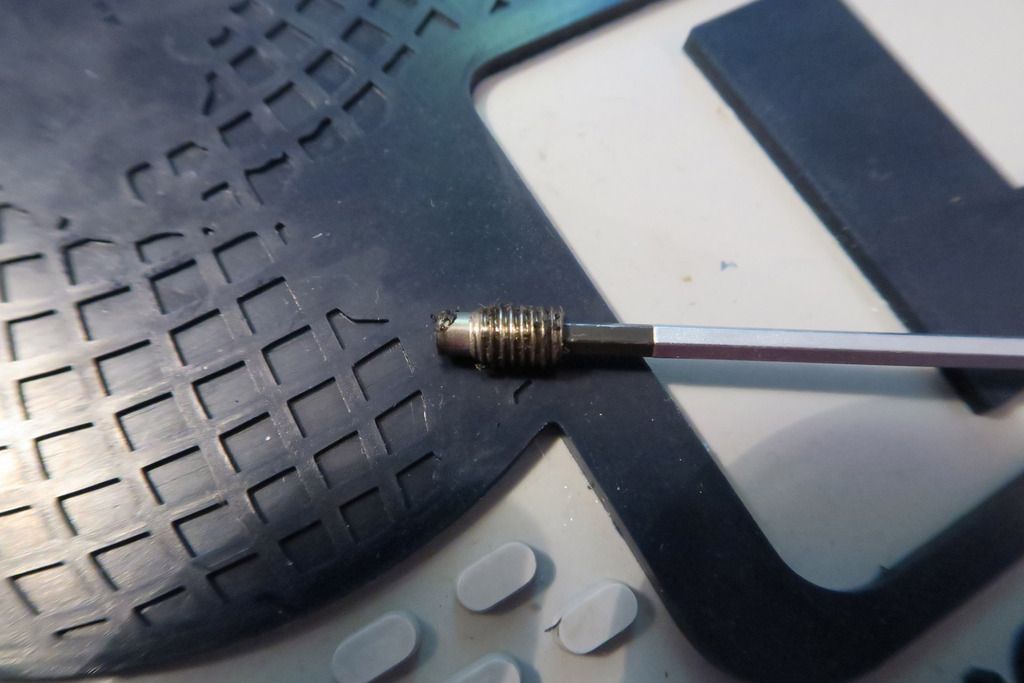
In fact, the nub at the end of the screw interfaces with a slot cut into the side of the shackle to hold it in place. You can go back and look at the shackle photo to see how that might work, or wait until the end of this post where I realise what’s going on and demonstrate it
Two main (bottom plate) retaining screws removed:
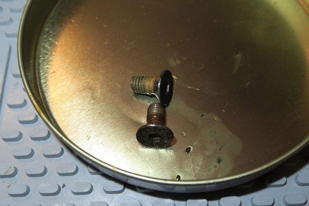
Rusty and blurgh – looks like this lock is going to need a good clean!
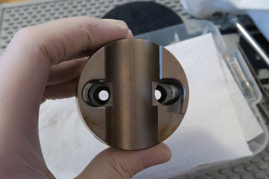
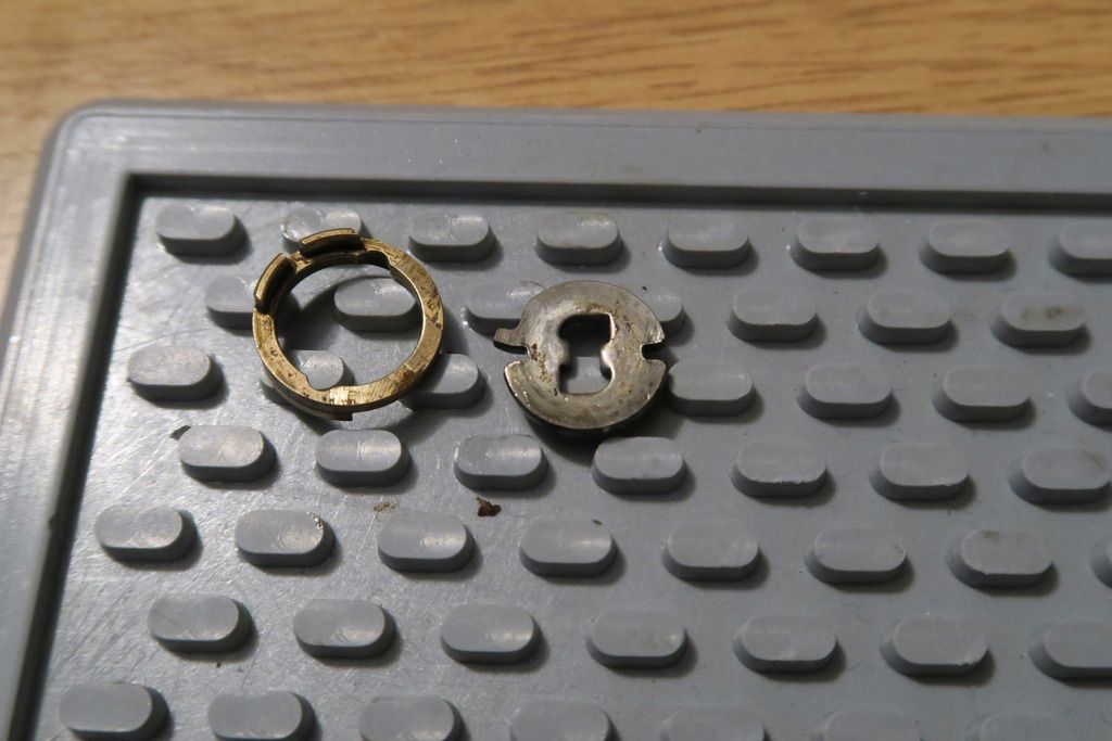
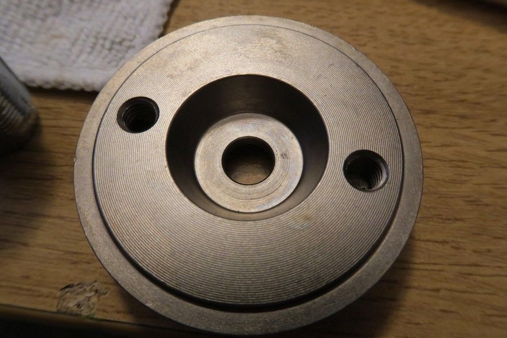
Here’s the bottom plate:
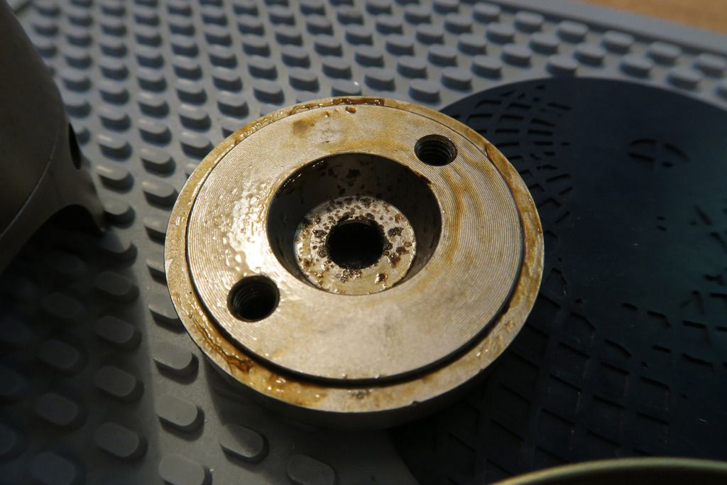
Unlike all of my other Rotaloks, this one did NOT fall off when the screws were removed, and couldn’t even be “shaken” out – I had to jam long hex drivers through the upper body hole and punch the bottom plate off! By looking at it, you can probably see why – thick with oil and grease.
Let’s take a look at the bottom plate cleaned up a little:
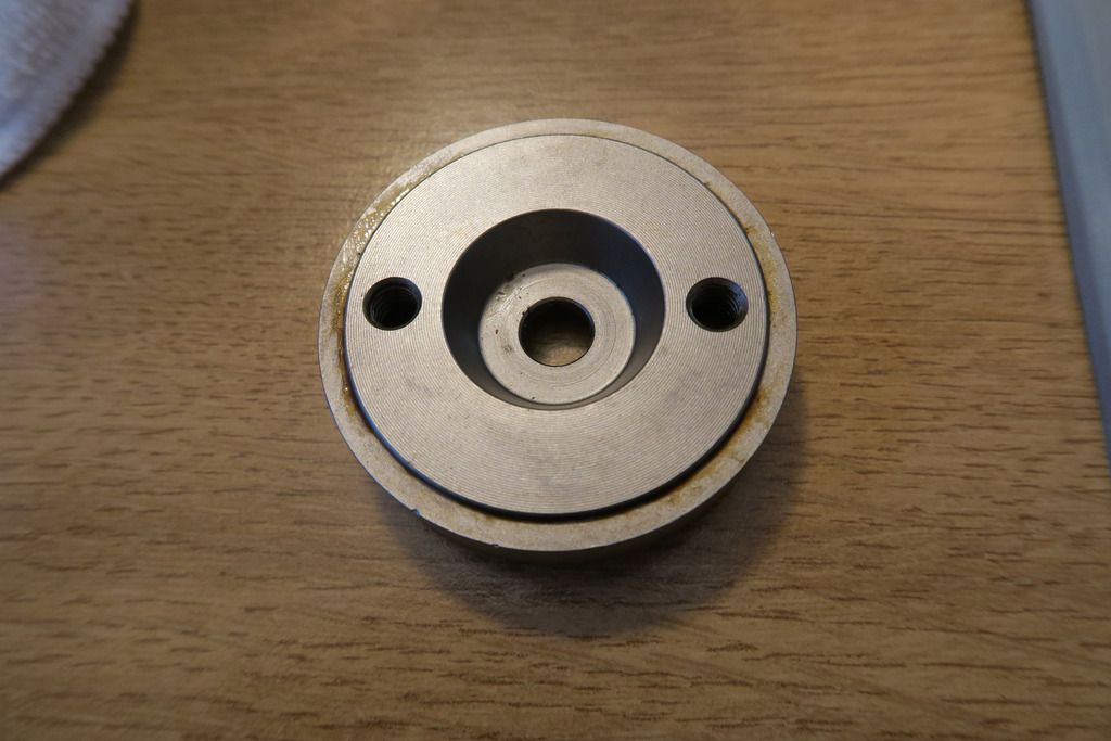
Now we can see much better how it’s formed – and looking at the odd core inside the lock body, we can see where that outer core body would sit inside this cutout, with the hole in the middle. I especially like this because it somehow feels more closed-off and protected than the by-necessity Z-style bottom plate cutouts.
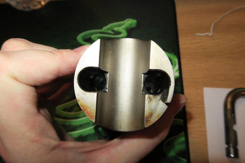
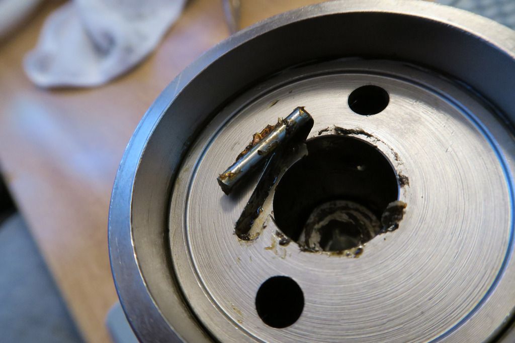
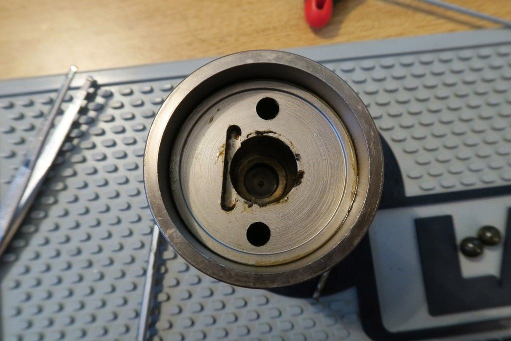
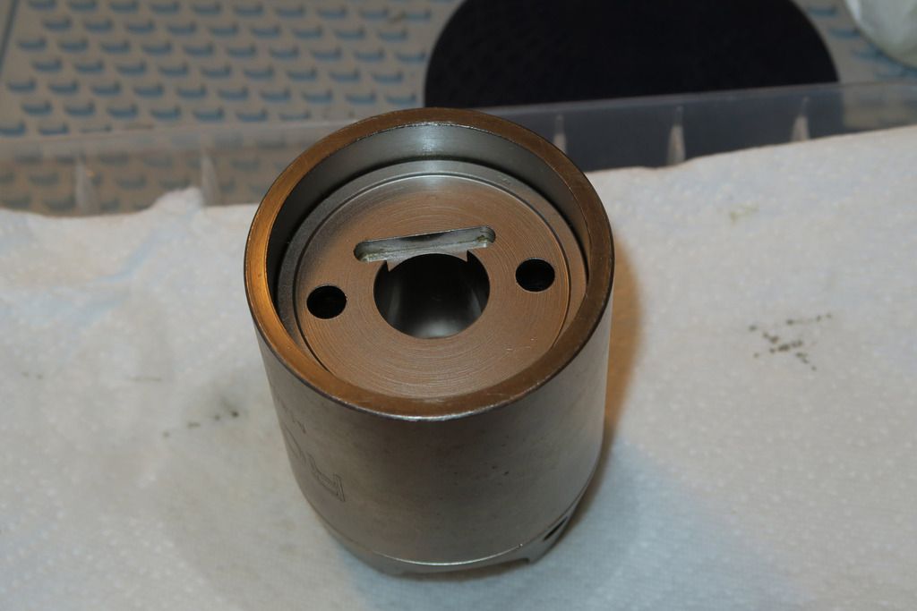
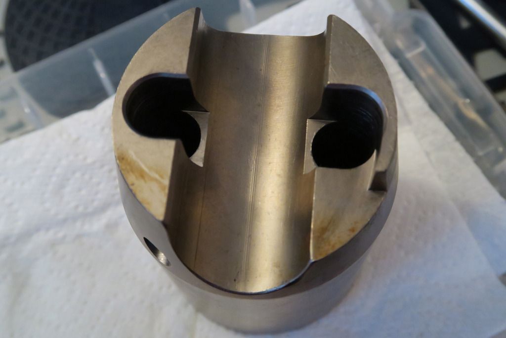
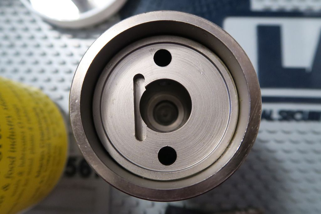
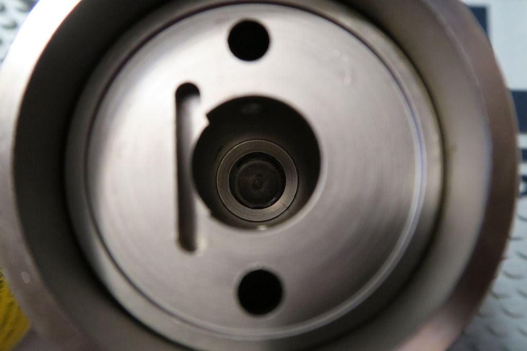
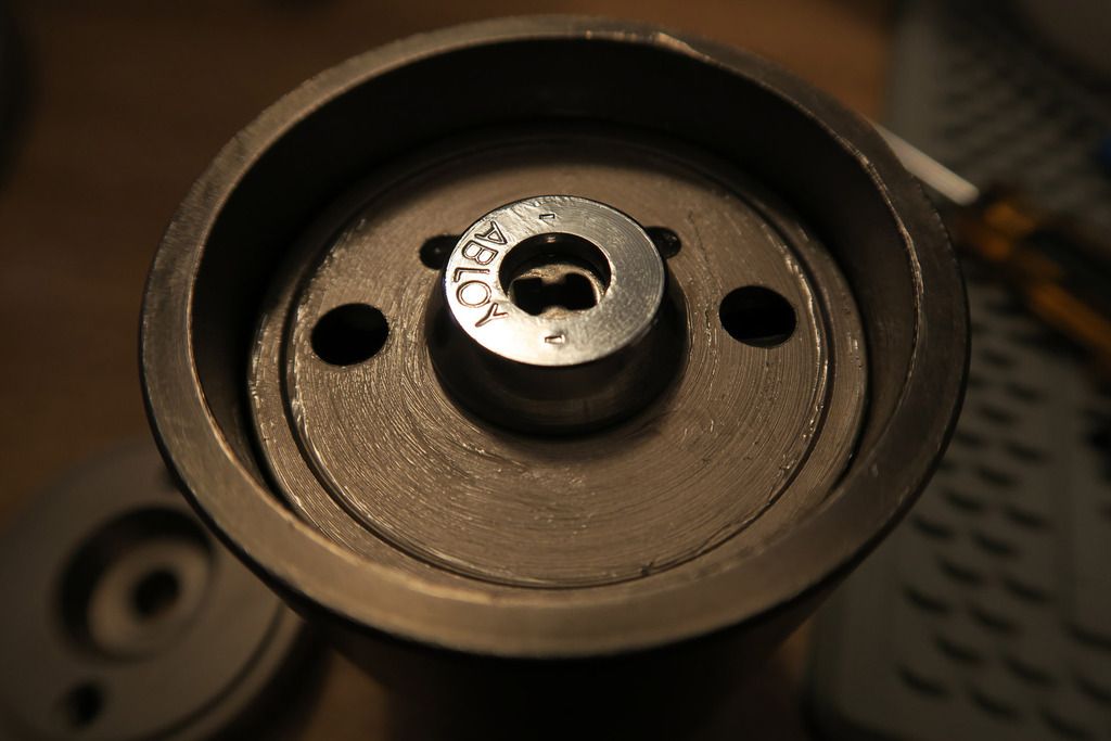
Minus the bottom plate, the underside of the Rotalok looks.... Unusual.
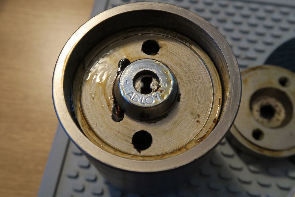
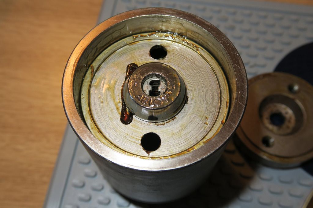
Yes, you have the typical “inner-bottom-plate” and connecting side-sleeve that forms the basis of the Rotalok body, as well as the familiar retention holes... But what’s with that vertical cut-out next to the core? And speaking of the core... That sure doesn’t look like a Euro cylinder! Time to investigate further...
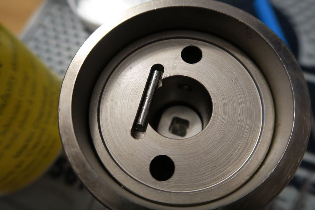
I actually forgot to take pictures of the removal but inside that vertical cut-out next to the core is a rod – partly to hold the core in and partly I assume as an anti-drill feature. It was a royal pain to get it out as the core would not move with the rod in place, and the rod was a nightmare to get access to with the core in place – I had to kind-of-shove the rod “up” along the cutout until it was clear enough to pull up the core bit-at-a-time and finally grab the rod and pull it out with pliers. Phew!
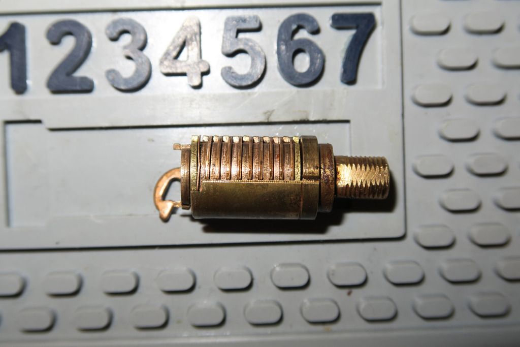
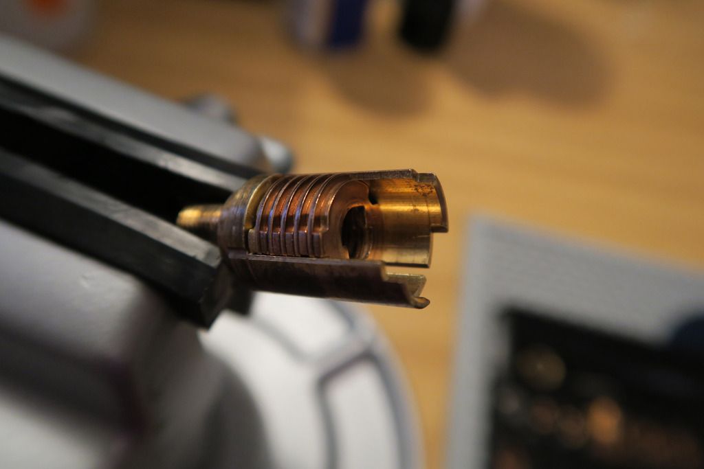
With that bit of drama over with, I was able to freely remove the core – and I was NOT expecting THIS:
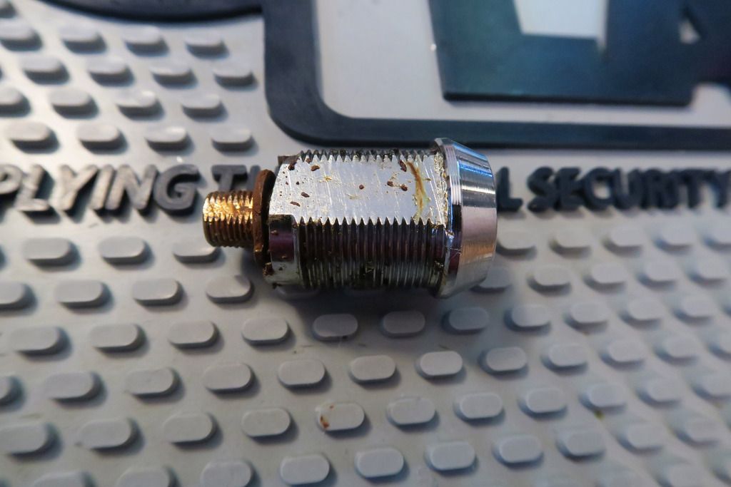
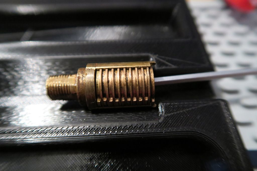
A cam lock! In retrospect, I should have expected this since I learnt (albeit afterwards) that the Exec core is designed for “padlocks and cam locks” and since the Rota is usually built for a Euro core, I assume they figured it was easier to shove a cam lock in there with an (I assume) specially-designed actuator. Another shot of that bad boy:
And a quick shot of the retaining rod next to the hole it came out of:
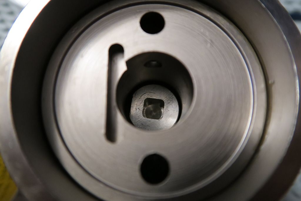
At the bottom of the lock body cutout you can see a big round thing with a square hole cut into it – that’s the special actuator:
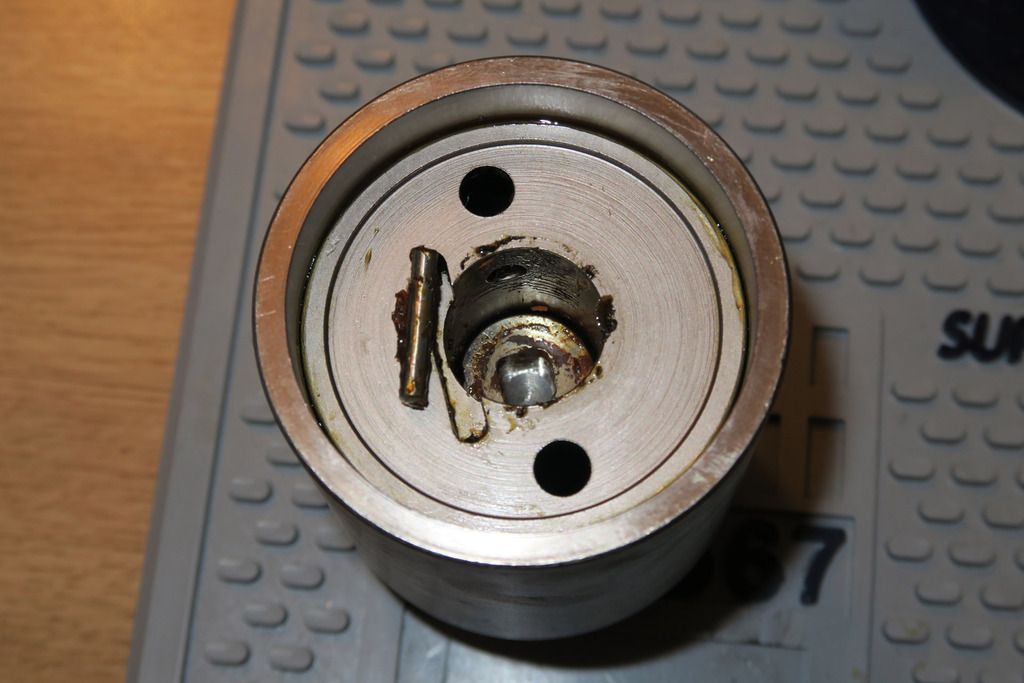
Also of note – you’ll notice that they didn’t just take a Euro-style body cutout and slap a cam lock in the round hole – the entire body is actually designed with the cam lock in mind, meaning that this lock isn’t just a bodge-together by a company or military – it was either designed as a special-order design direct from the Rotalok people (whether that’s Pickersgill-Kaye, the current owner of Rotalok, or an older owner, remains to be seen) or was at some time an actual production model – but I’ve never seen this variant before. Given that these locks are usually used in sensitive areas such as prisons, military bases and government buildings I guess that makes sense – they’re probably stored or destroyed when no longer needed to protect the security!
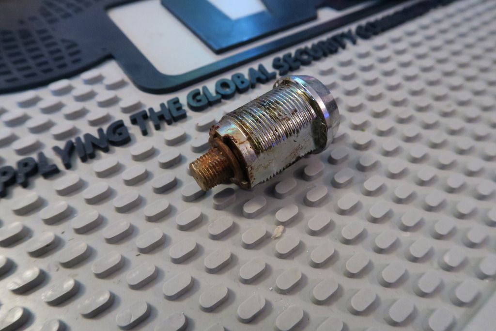
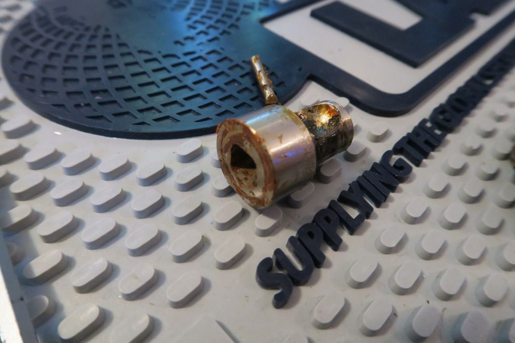
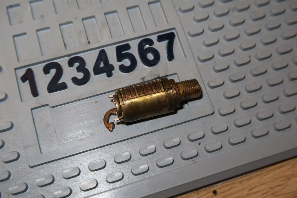
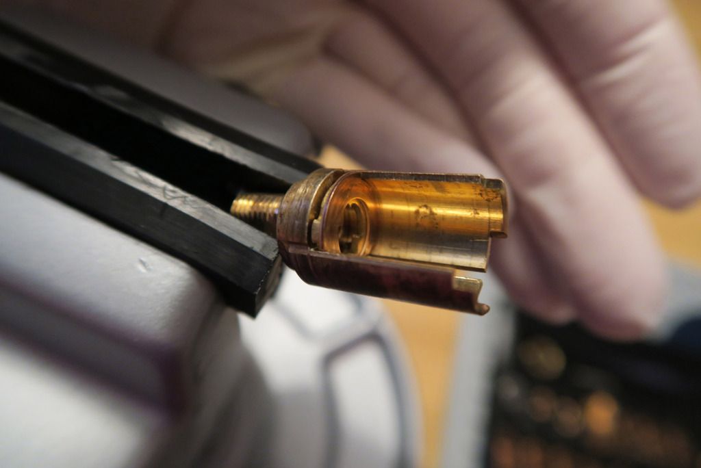
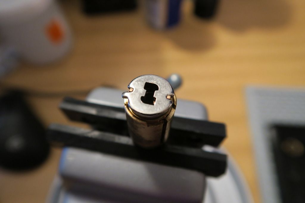
Here’s the actuator, removed from the lock:
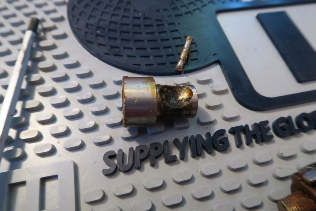
The wide part on the left hand side is what you saw when looking down into the lock – in other words, the end of that part has the square hole that interacts with a bolt at the end of the cylinder. The right side, as you can see, has the usual cutouts for the ball bearings and ends in a smooth surface at the back of the lock:
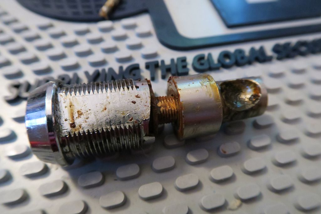
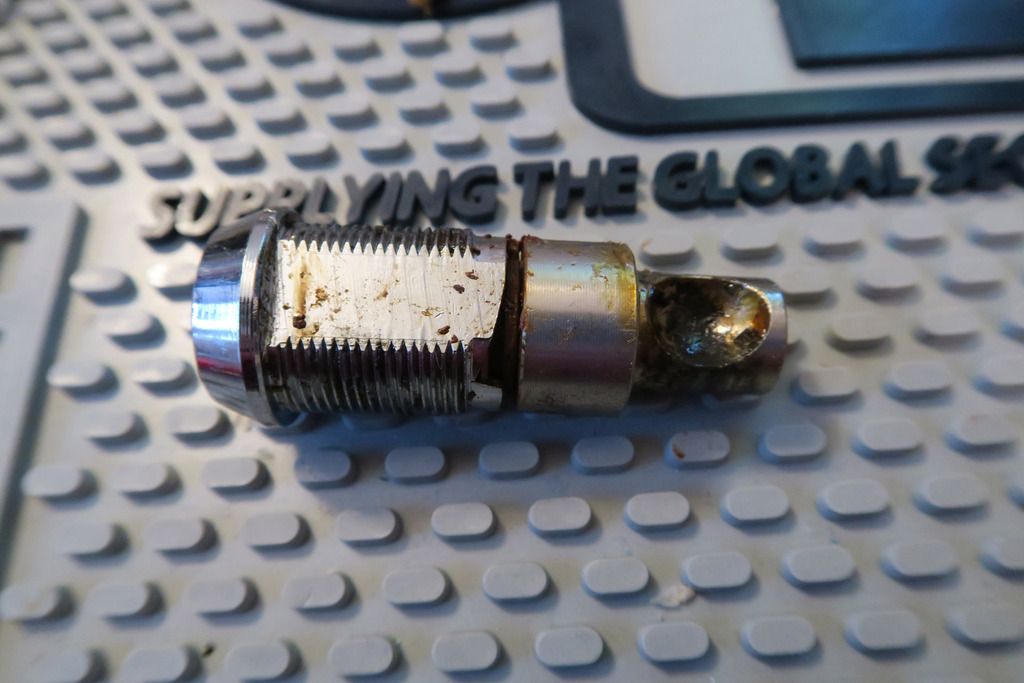
The bolt at the back of the cylinder slots into the actuator like so:
Despite the round external body on the cam lock, the outer body does not turn, but instead when the key is inserted it interacts with the disks held inside a disc carrier – this carrier is attached to the rearmost square bolt, and when the disk carrier turns (which is enabled by clearing the sidebar into a slot in the disks and disk carrier, from a cutout in the inside of the outer body), so too does the attached bolt, which rotates the cam, freeing the ball bearings in the usual fashion.
Here’re the ball bearings from inside the body, after removing the cam:
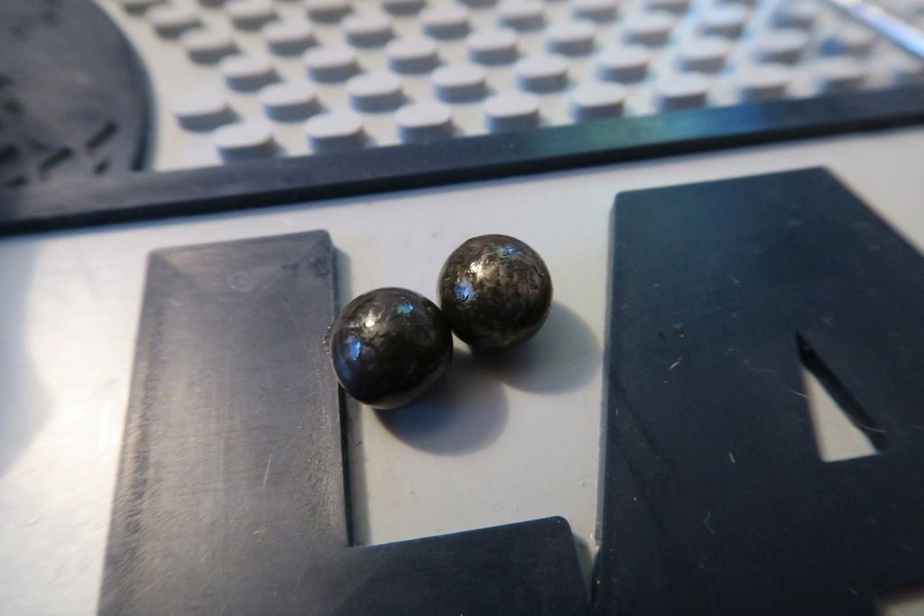
As you can see, they’re covered in some kind of oily black stuff. I’m not sure if this is the natural colour of the lube used here, or just a combination of the lube plus atmospheric contaminants (or even just dirt and grime with no lube used at all formally – shudder!), but this inky black stuff covered everything inside the lock and was a real pain to clean off! The oil coming from between the outer skin and the body (you can usually “generate” some by spinning the outer skin back and forth a bit until some oozes out from the gap between both in the inner body, against the bottom plate attaches) is an orangey colour – still not nice, but not the black stuff you see here, so luckily it didn’t intrude into the impossible-to-disassemble-or-clean (seriously – how DO they put these things together?) area between the outer sheath and inner body).
Bottom of the lock cleaned a little – just with some tissue paper like I did with the bottom plate. It’s not a full clean but it helps us see what we’re doing:
You can also see the orange lube stuff leaking through on the right hand edge.
I didn’t show the cleaning process for the body as it wasn’t especially interesting, unless you count mountains of cloth/paper towels, GUNK, WD-40 and swearing as interesting! We got there in the end though – here’s the finished results for the body:
Looking down inside:
Outer body (light clean with WD-40 and a cloth):
Rust spots – can’t clean those easily unfortunately:
Rust on the top – I did manage to scrape it away a little but don’t want to risk using Jenolite and turning the whole thing pink!!
Looking much cleaner overall though:
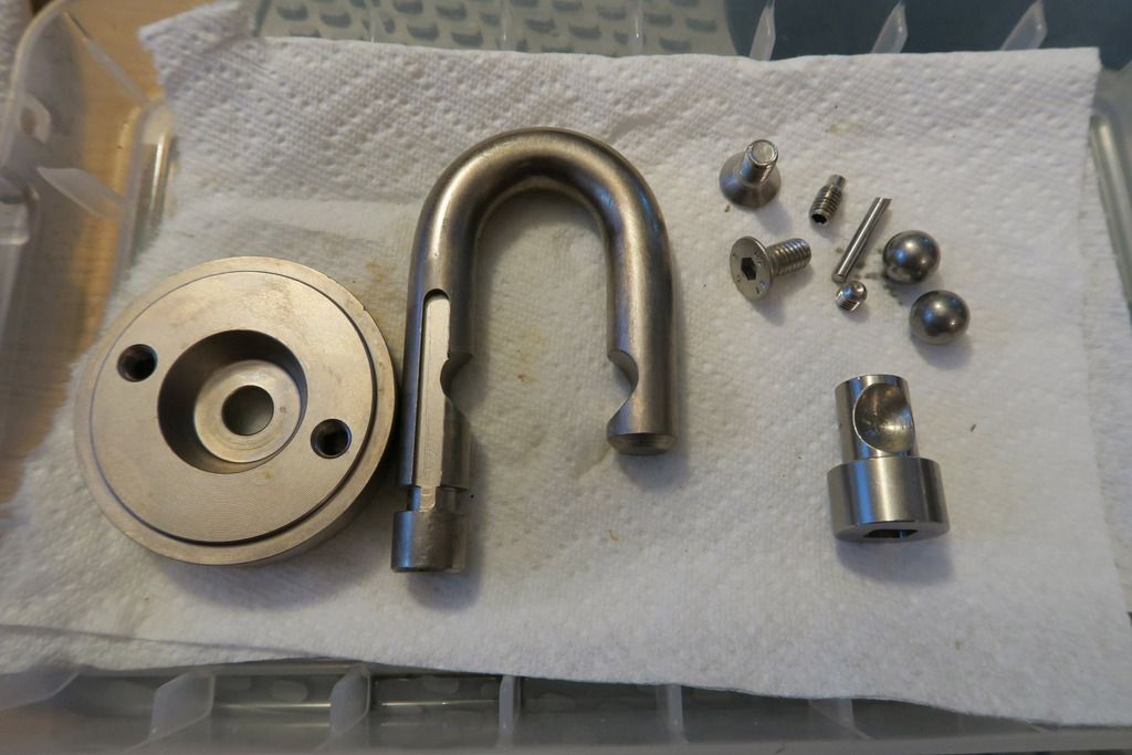
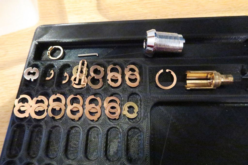
Bottom plate, shackle, bottom plate retaining screws, shackle retention screw, cylinder-lodging bar, other outer body screw, ball bearings and actuator cleaned (in roughly left-to-right, up-to-down order):
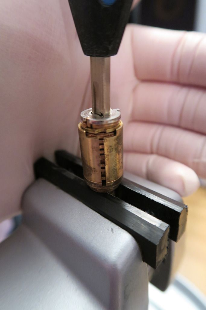
Time to tackle this beast – with this much grime, there’s no getting away from it – we have to strip and clean the core!
Should be a fun exercise as I’ve only stripped one other Abloy core – the 656, which I believe was a High Profile (the predecessor to the Exec), and that was an interesting case by itself – so it’ll be cool to see how this one compares!
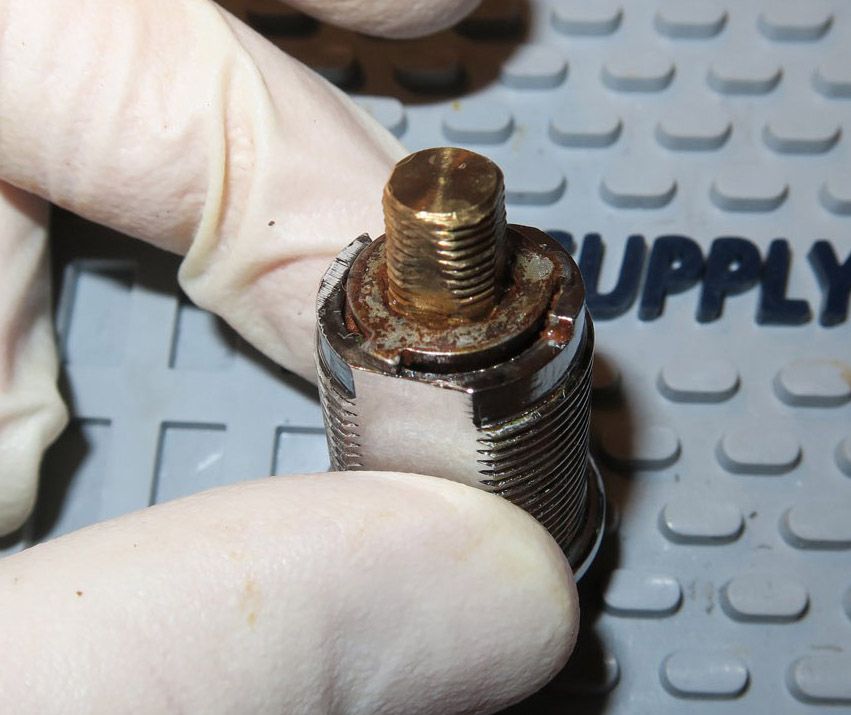
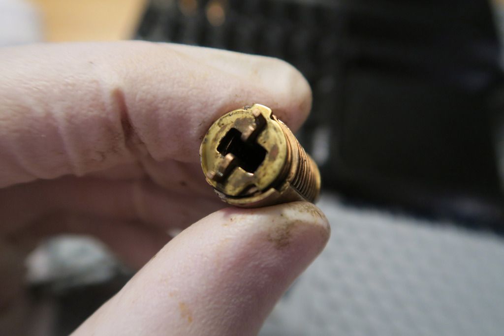
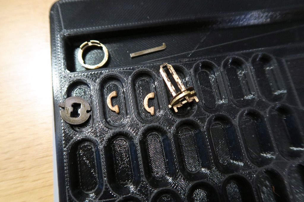
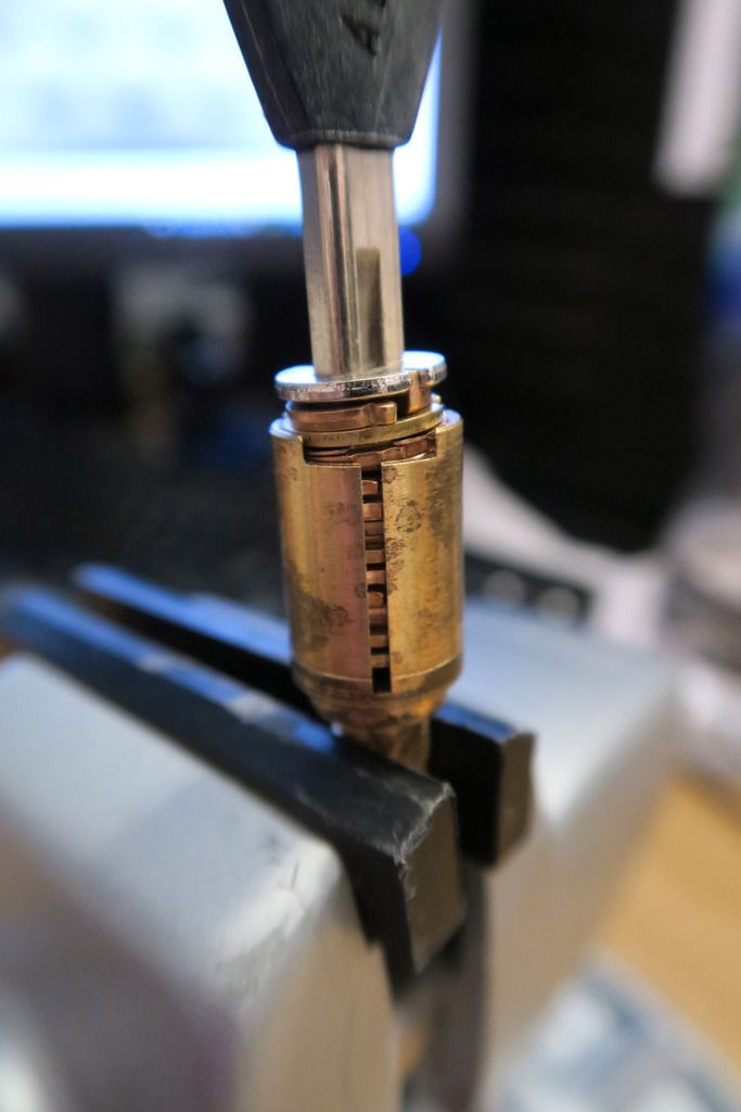
First off, on the previous picture, note the brass bolt sticking out of the top (which turns the actuator), and the rusty disk that’s the first thing at the back of the core – sharp-eyes readers will notice two nubs sticking out of this ring, and a nub sticking out of the back of the cylinder housing at the 3 o’clock position – that ensemble is what controls the range of motion for the cylinder, as the disks turn the nut on the bottom left with rotate counter-clockwise and jam on the cylinder housing nub after approx 90°, preventing further rotation.
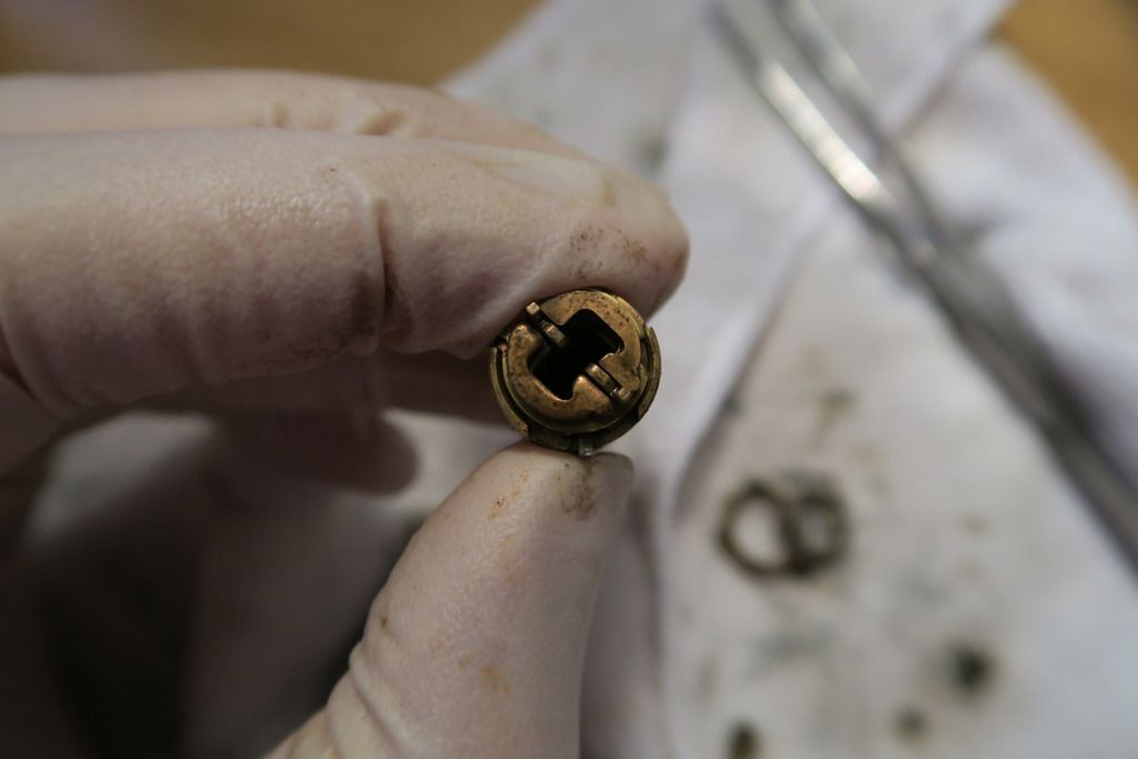
With that disk removed from the cylinder, it’s easier to see the nubs on it – and the rust, sheesh!
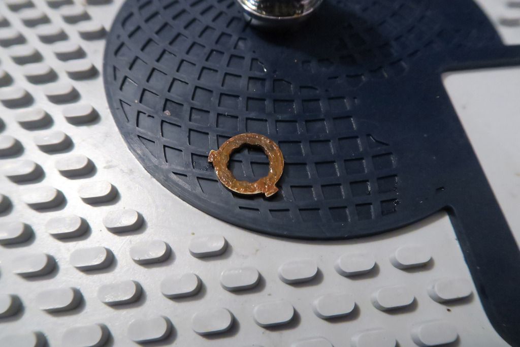
The flower-pattern cutout inside is to allow it to fit in multiple positions on the bolt (no matter where you insert it, there will always be a “square shape” of cutout notches to allow the bolt to slide in. Pretty clever!)
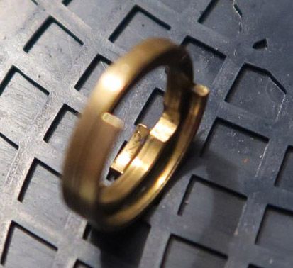
Back of the cylinder with the rotation-blocking disk removed:
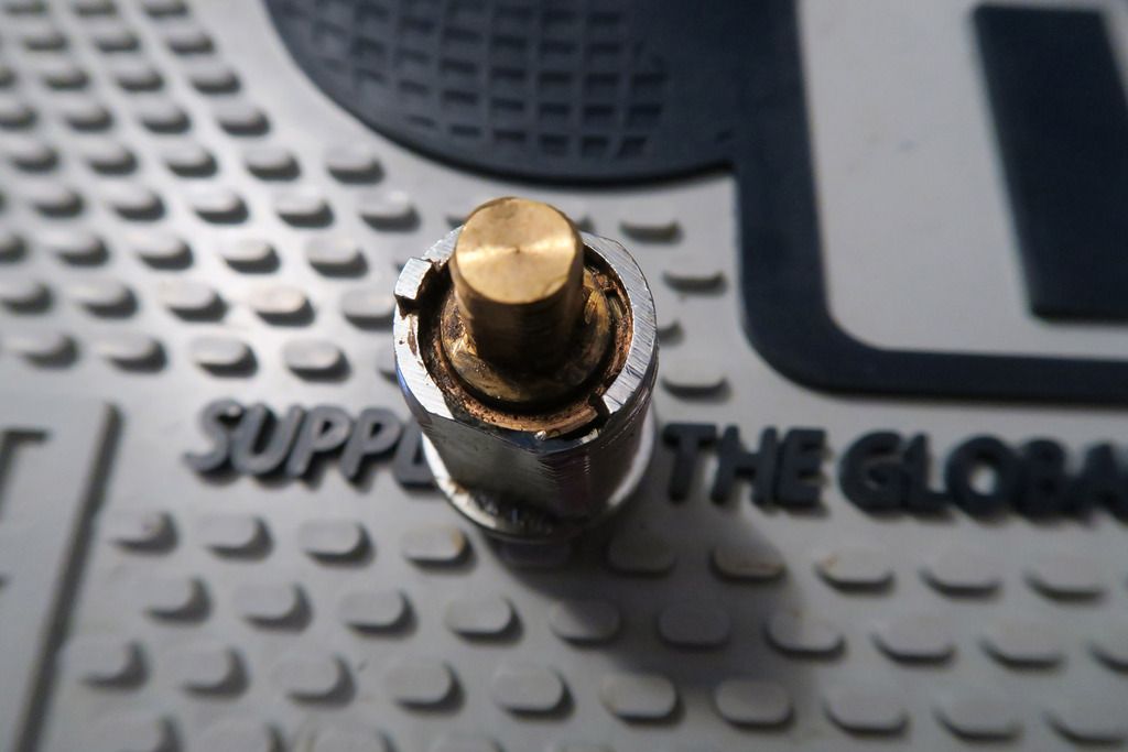
The especially eagle-eyed will notice the next disk down – it’s one of those rotating C-clips (note the little notch in the disk at about the 1 o’clock position). To remove this, we rotate it (with a small spike or screwdriver) until the square end lines up with a slope cut into the outer body and then kind of lift/rotate it until it starts to slide up the ramp:
And keep rotating until it’s off:
With that removed, we can just tip the disk carrier out – here’s the front plate (mostly – it left a couple of disks behind, leaving me scratching my head a little as I’ll explain later!):
This disk:
Is part of the DSS mechanism, to prevent the cylinder from turning when the key isn’t fully inserted. It sits at the front of the disk pack and... Well, we’ll get there
The next disk in line is the front alignment disk, which aligns the key so that it will fit properly into the disk stack – it also interacts with the side-rod-thingies, I assume to rotate all the disks at once (so this is where the lock tensions? I’m not 100% sure about this yet).:
Here’s the rest of the disk stack, inside the carrier (the two half-parts, which are for the DSS, have fallen off here):
On the stack, you can see the key disks (the lower ones) and the spacer washers inbetween (the higher-up, more copper coloured ones) which prevent each key disk from pushing and rotating the others.
Another shot of the cylinder – you can see the half-piece that fell off more clearly here. There are two of these:
Front of the disk pack with the profile disk and two half-pieces removed:
The next step is to pull out that long rod (you can see the end of it and the two sticking-out nubs in the last pic). When I did this, the last key disk and washer came with it and I couldn’t convince them to leave so I just left them there!
You can also see the front DSS ring (top left), sidebar (Top second-left), profile disk (second line, position 1), left and right ½ disk (next to the profile disk), and the rod thingy
.
With all that stuff out of the way, here’s the rest of the disk pack – just the essential stuff!
(Holding it on with a hex driver in case they all decide to fall out and go everywhere, hahah!)
Then,
carefully, we remove each disk-and-washer pair and lay them out (in this case going from left to right, up to down as they come out of the stack from the front, meaning the “last” disk (bottom right) was at the back of the cylinder, nearest to the bolt):
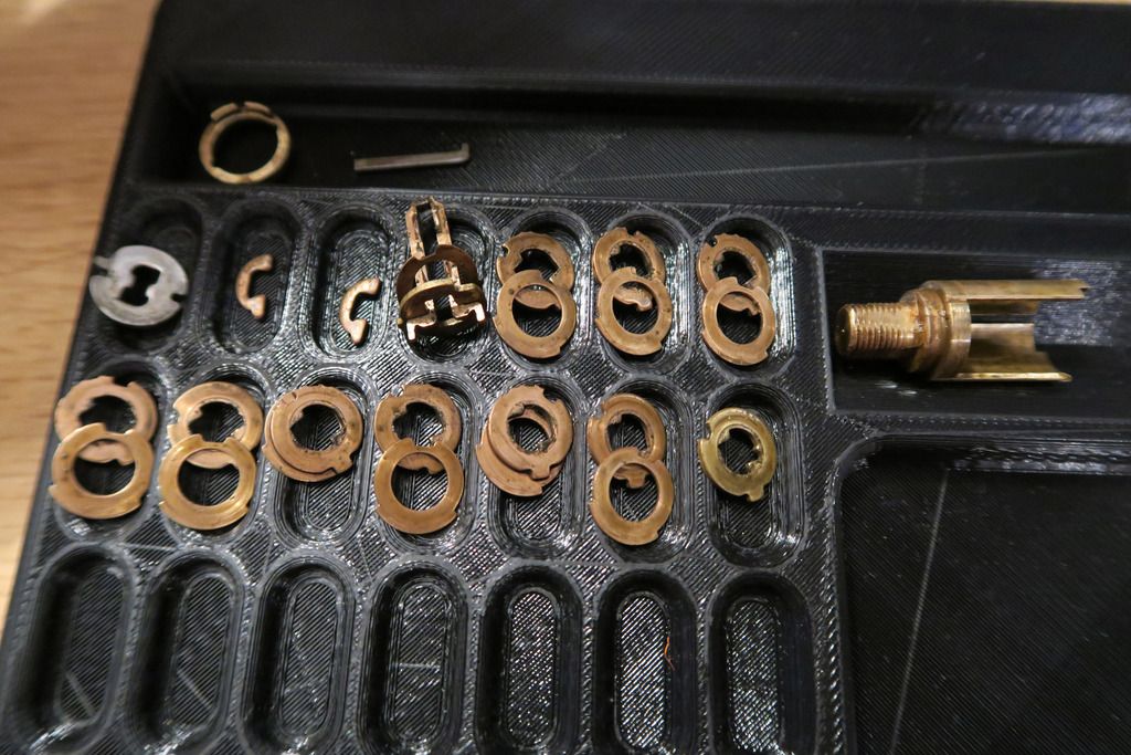
Closeup of some disks:
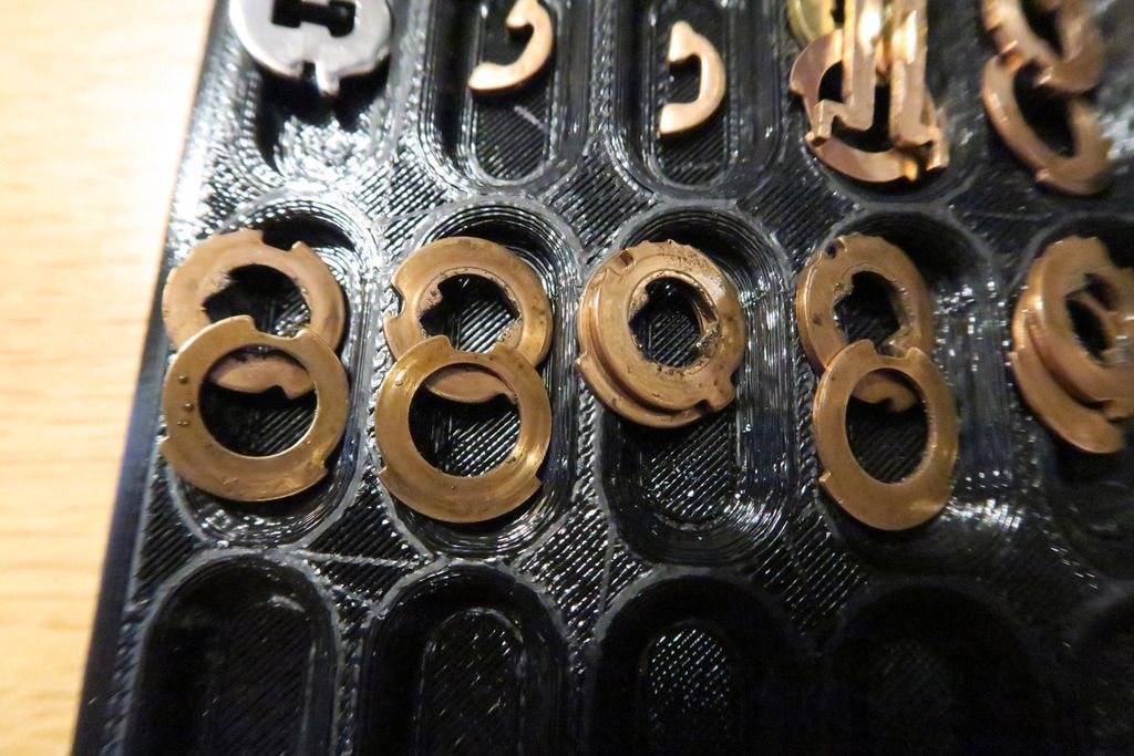
You can see the black grime – you can also see the false and true gates on the key disks (the little “nibbles” on the outside of the disk in one position, and one “big” nibble for the true gate), as well as the nub that sits just in the cutout gap in the disk carrier body and stops the disks rotating more than they’re supposed to. The cutout in the spacer disks (washers) is to allow the sidebar to slot in properly.
I then set up a little workstation – four small pots with WD-40 in, each to take a key disk and washer pair (to keep them separated from each other and also in the correct order). After having a dunk in that I’d give them a preliminary wipe off, then dunk them again and repeat that 3-4 times until they’re clean, then return them to the pinning tray. After all four pots are done (to avoid confusion), I’d add the next 4 sets and continue:
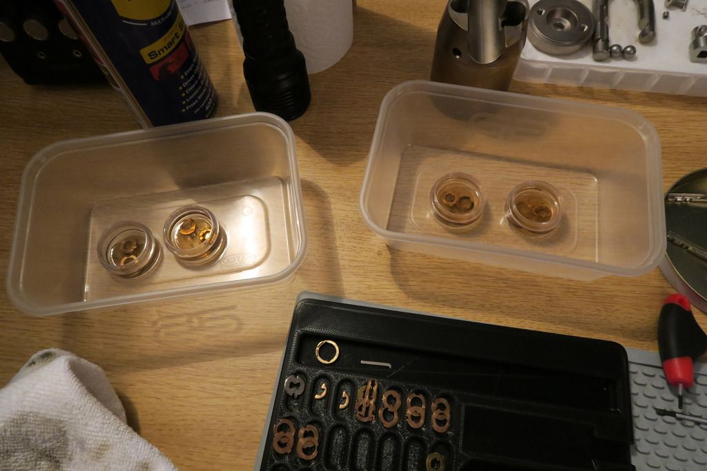
...Until all the disks are clean – along with the other parts (cam lock body, disk carrier, c-clip, DSS ring, sidebar, disk rod and all the disks and washers):
Oh, and the keys. Can’t forget those or we’ll just end up introducing all the grime back into the lock!
All the parts cleaned:
(obviously the body was also cleaned using the usual methods – spray in some WD-40 carefully, use a cloth mounted on a screwdriver to shove into all the holes and wiggle about, remove, pick a new bit of cloth and repeat ad nauseum.. heh!)
Just for fun, looking at how the cam lock front fits into the bottom plate:
Oh, with the bottom plate properly cleaned we can see the manufacturing rings cut into it, pretty cool looking IMO:
Also for fun, looking at the cylinder in the body (no disks in it yet):
You can also see where the side rod would go, and if you can imagine how it’d bind up on the outside of those screw-like rings on the outside of the cam body – yeah, fun times!
Okay, time to start cylinder re-assembly!
Like with the disassembly, we put the disk carrier in a vice to make it easier to add the disks with the help of gravity. The rearmost disk (already inserted) is actually not a key disk at all (i.e, it’s not cut to a certain bitting and the key doesn’t have a unique cut to actuate it) – instead, it’s used to guide the tip of the key and also for the disk controller.
Filling up the disk stack!
Disk pack fully assembled:
This includes the front profile disk, which, along with guiding the key in correctly, is used for key profile purposes, so that unique key profiles can be developed (for higher/differentiated security tiers and military use etc). If the key profile is incorrect, it won’t be able to enter the front cutout. You can also see the “arms” from that rod sticking out of the left and right side at 3 o’clock and 9 o’clock positions (I assume this is used to help the entire stack rotate together).
Now we just insert the key in the locked position:
And rotate it until it stops, and then the sidebar gap will be empty!:
Or... Not. Seems that while cleaning I got some disks flipped upside down, and whilst the key will still fit into them, they now don’t align correctly. Gah!
So, down the stack we go, taking the disks out and placing the back on the pinning tray. Reassembly this time involved adding a disk (rotated furthest anti-clockwise to the “locked” position”), inserting the key, rotating to stop and checking the sidebar cutout. If it isn’t clear, remove and flip the disk and check it again. I’m sure there must be an easier way to tell but I couldn’t figure it out!
Eventually, after lots of checking:
Woot! We have a clear sidebar slot
.
Add the sidebar to be sure:
Okay, now it’s time to explain the operation of the DSS. First we need to add the DSS outer ring, and the two half-parts:
Notice how the outer ring has two small indents cut out of it (roughly 12 o’clock and 6 o’clock positions), and that the ½ disks have little hammerhead ends on one end, which had a nub that sticks into that cutout? Remember how the key had a dimple-cut near the bow? When the key is inserted and rotational pressure is exerted, the DSS ring will push on the rounded edges of the two inner ½ disks and try to push their outer nubs down and into the cylinder space. If the key is inserted correctly (all the way in), the inner part of that hammerhead nub will slip into the dimple cut on the key, the outer nubs will clear the cutout hole in the outer DSS disk, and the cylinder can turn. If the key isn’t inserted properly, the inner nubs of the hammerhead parts of the ½ disks will jam on the key metal, preventing them from falling in and thus preventing the outer nubs from clearing the DSS disk, stopping the cylinder turning. Simple but ingenious!
Disks from an angle:
When I was first re-assembling this, I forgot to add that outer DSS ring and whilst it went together, I couldn’t figure out why the ½ disks were flopping around into the keyway. I first encountered these ½ disks on the Abloy 656 that I stripped and never really figured out what they did until today after I read Han Fey’s useful guide and found the outer disk again, and put two and two together! Got there in the end
.
Then we just pop the profile disk on (making sure that it’s the right way round!):
And slot the carrier back into the cam lock body (with the sidebar positioned in the sidebar cutout of the body, forgot to photo that!):
Looking shiny and clean!
We then reverse the steps with the c-clip, sliding it back into place, and replace the limiter ring:
Note that you’ll want to take careful note (maybe a photo) of the position that the ring is in relative to the back of the lock body before you disassemble, so you can re-assemble the same way – I suspect you’ll have problems if you put it on in the wrong position!)
Notice also how this is the one ring that didn’t really clean up. It was super rusty so I bathed it in Jenolite for a while – didn’t turn the disk pink, and it DID get rid of the rust, but left an ugly grey exposed metal surface underneath. Bah!
Oh, one final note – when I was first testing this, I forgot to put the limiter disk on the back as well as the c-clip whilst testing that the lock worked, but found that I couldn’t remove the key. After AGES of fiddling, I figured out how to get the key out – the limiter must be in place (to stop the key from endlessly spinning and not being stopped at the removable point (where the sidebar aligns with the cutout in the body)), and without the c-clip in place the disks were shifting around and I had to actually pull the core body manually back whilst pulling the key forward – totally unintuitive and also my fault since I should have put both parts back on before testing (although putting the C-clip back on is a pain especially if you aren’t yet sure whether it’s going to work). Just remember if you get stuck in the same situation – drop the limiter disk back in the right position and pull the core body back whilst pulling the key forward (out). Neat trick!
With that over and done, it’s time to re-assemble the body!
You can see where the core fits and how the side-bar (not the sidebar!) will jam up against the edge of it, cutting across that hole. I am assuming that the main reason for this is to stop the core jiggling around and also to protect from the bottom plate being drilled out around the core’s edge and then it being pulled out?
Better shot of the back of the lock – fairly normal from what I remember of the other Rotaloks, apart from being round rather than Euro-shaped. The lip at the back is where the break in the middle of the actuator fits, between the rear part (which interacts with the ball bearings) and the front part which connects to the rear of the core:
Pop in the ball bearings, slide the actuator in:
Pop in the sidebar:
Side the core down.....
Ahaha no, of course it’s not that simple. See how it doesn’t quite fit? Basically you need to put the core in most of the way, then start to slide the bar in from the side, then kind of ram-jam both parts bit-at-a-time until the core is in all the way and the bar is in the right place. Oh, and don’t forget to make sure the core isn’t in upside down, and that the actuator is in the right position of 4 possible ones (the hole is square – although possibly 2 of 4 positions would work, untested), and that the bolt is going into the core properly – a fun challenge ¬_¬.
Finally in!:
Lube up the inner lock body/bottom plate area:
Now we’ll demonstrate the shackle retention mechanism that I mentioned earlier. In previous Rotaloks, a small grub screw held in place a long metal rod that went through the body. This rod will slide along a squared-off edge of the shackle but will jam on the fully rounded part at the bottom, preventing removal.
In this lock, the shackle instead has a slot cut into it, and when the grub screw (no rod this time) is fully screwed in, a nub on the end of the screw will sit in the groove and prevent it from coming out:
(Obviously, the groove doesn’t go all the way to the end!). As far as I know, this is an older lock (due to the older Exec cylinder) so maybe they had a problem with the screw loosening and the shackle falling out? Or maybe they’re just two totally different designs and not influenced by any failing of one or the other. Or possible a patent issue – who knows!
With the cylinder in place, all we need to do now is screw on the bottom plate* via the inside screws and attach the shackle, securing it with the grub screw as described:
 (* unlike the other Rotaloks, which use a Euro cylinder, this Rota doesn’t have any issues with screwing the bottom plate on too tightly. This is because with Euro cylinders, the entire front of the core rotates, and since this parts contacts the bottom plate, if screwed on too tightly (or the core or actuator are too long) the front of the core will jam up on the bottom plate and not move, squashed between the bottom plate and the actuator / back of the lock cut-out. However because cam locks have a solid main body and it’s only the disk carrier inside that moves, even if the front of the cam lock body is jammed tight up against the bottom plate, it doesn’t matter as that part doesn’t rotate anyway).
Lock re-assembled:
Bottom plate and cylinder front after cleaning:
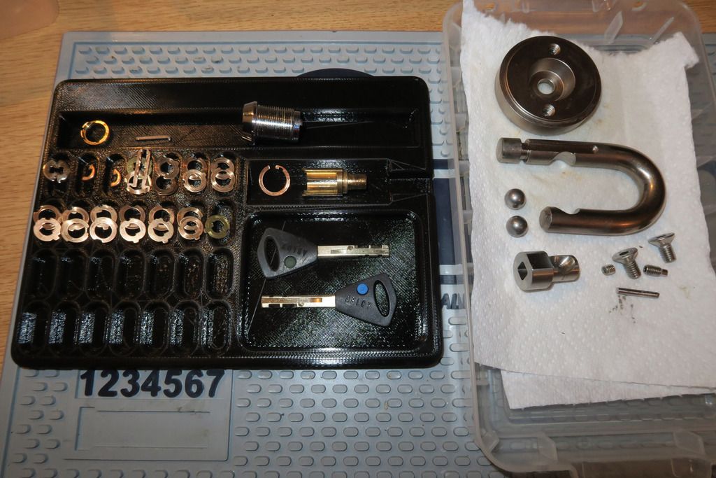
Lock and keys:
Tagged and ready for the lock board:
And that about does it for this write-up! I was super excited to see this for sale and even more excited (and bewildered) once I got it apart so I hope you enjoyed reading along!


