


![]() Tue Mar 15, 2016 11:11 am
Tue Mar 15, 2016 11:11 am
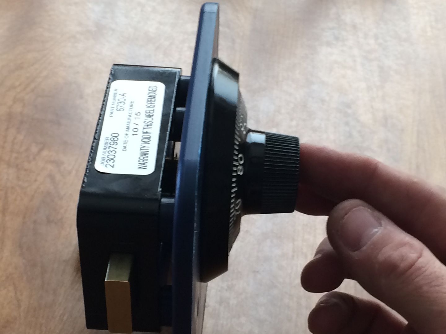
Installing A Sargent & Greenleaf 6730 Safe Lock
How To Mount A Sargent & Greenleaf 6730 Safe Lock
Recently mounted an S&G 6730 for another member, and decided to make a post to demonstrate how it is done.
The project requires few parts and fewer tools. There are some tools that would make it a easier to mount on a safe door, such as a dial ring alignment tool. But don't have one.
The tools are a phillips screwdriver, a hacksaw, a small file and a marker. You will need the safe lock, dial, dial ring and dial ring bushing.
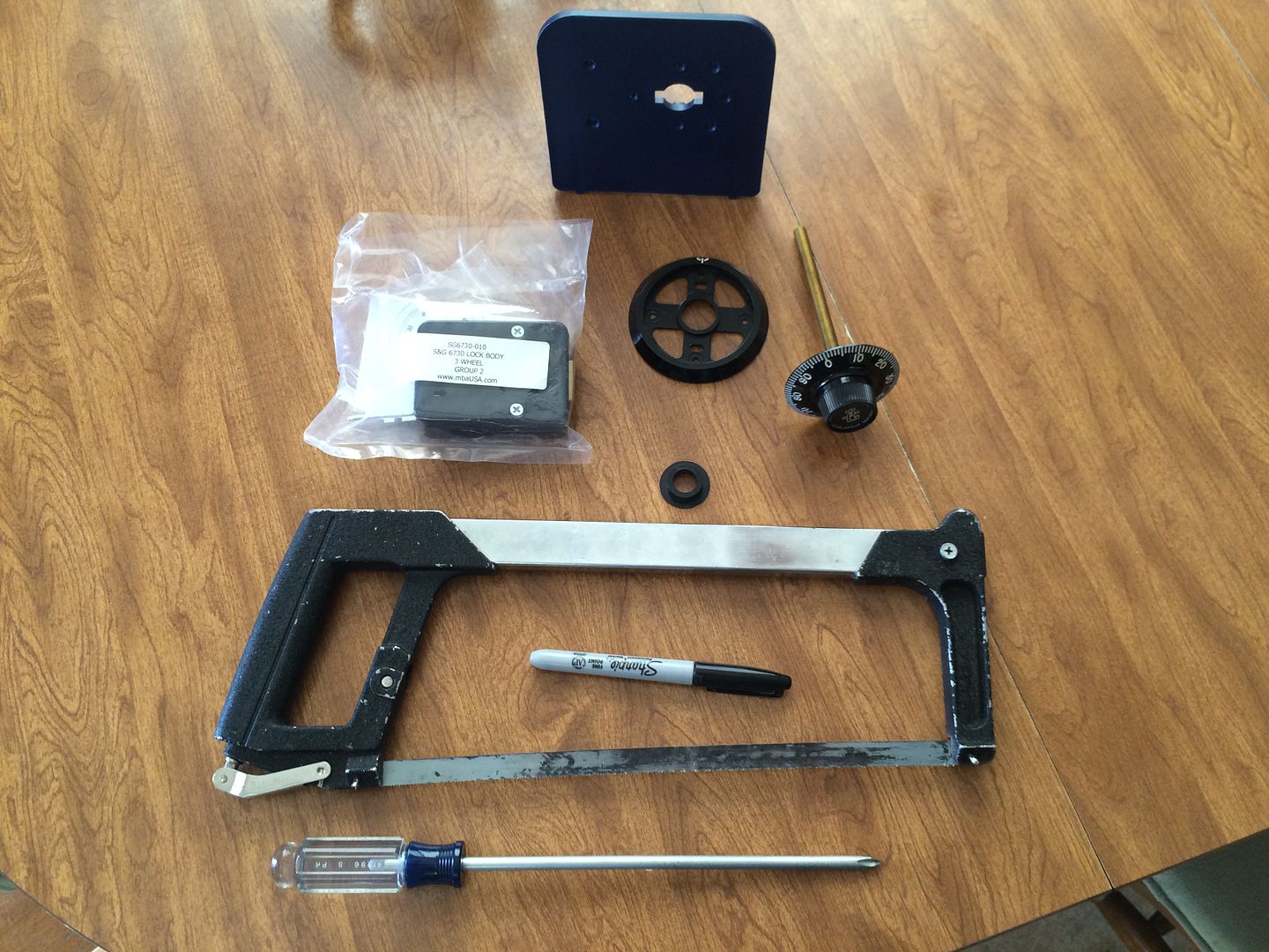
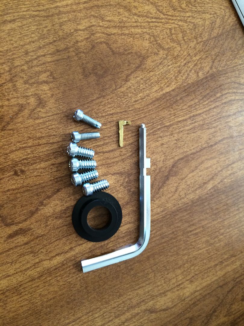
And the screws, spline key and a change key (to set the combination).
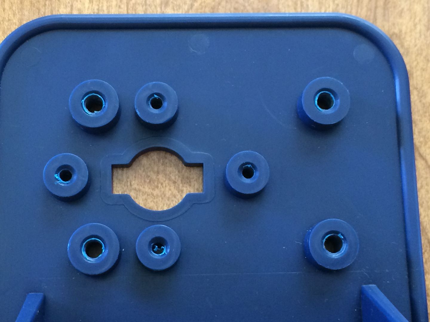
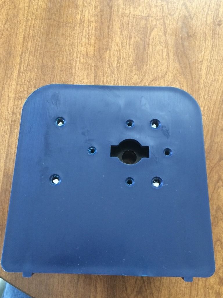
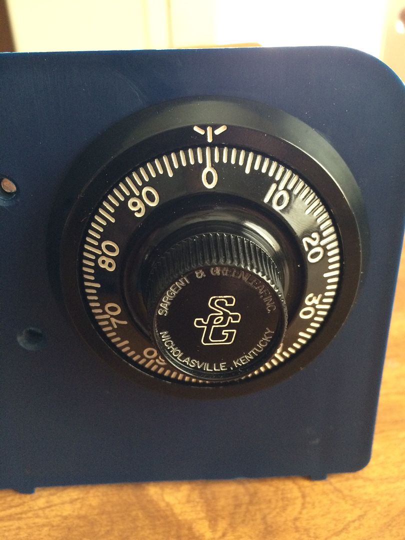
This is the mount we will be using. This mount already has holes drilled for most modern safe locks and dial rings.
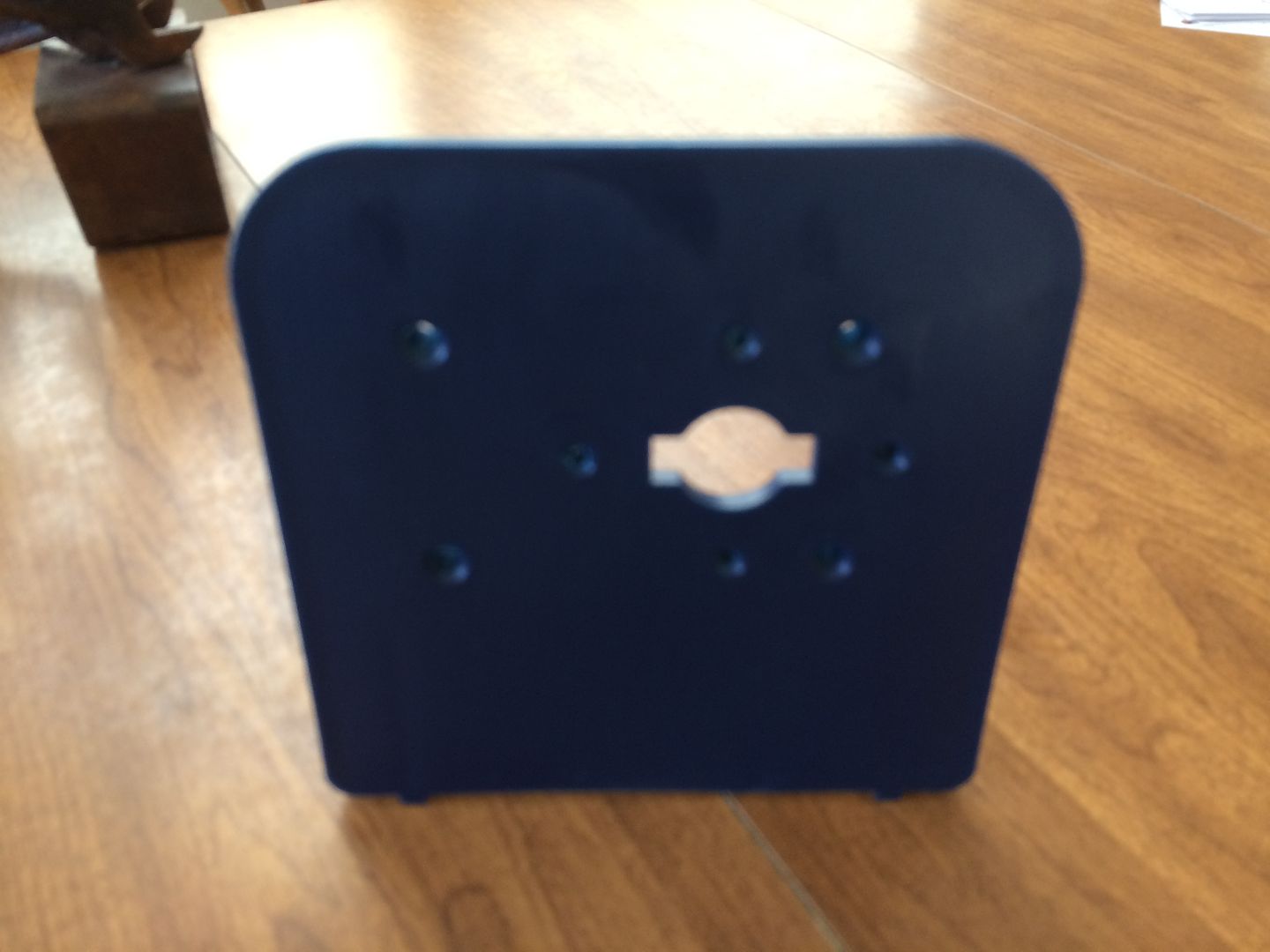
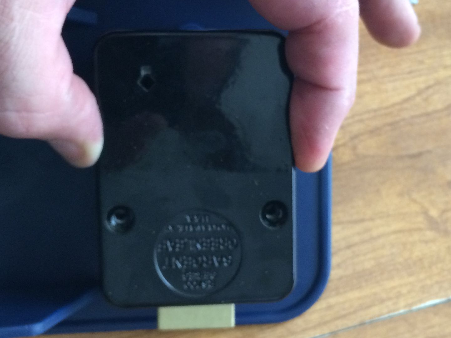
The back of the mount.
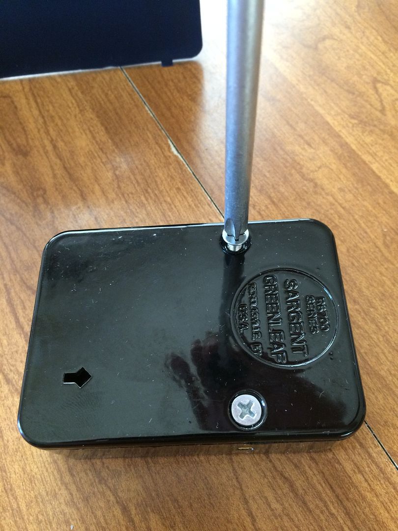
Let's get started. Take the two screws off the back of the safe lock.
And remove the back cover.
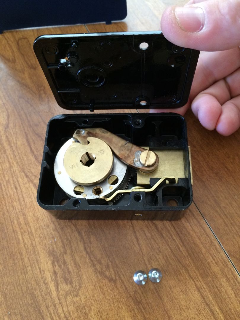
This is the drive cam.
It lifts right out.
Place the lock body where it will go on the back of the mount (or safe door).
Install the four screws that will hold the lock body in place. They go in the four corners of the lock, and will fully seat against the front of the lock body. (You are looking from the back of the lock when installing).
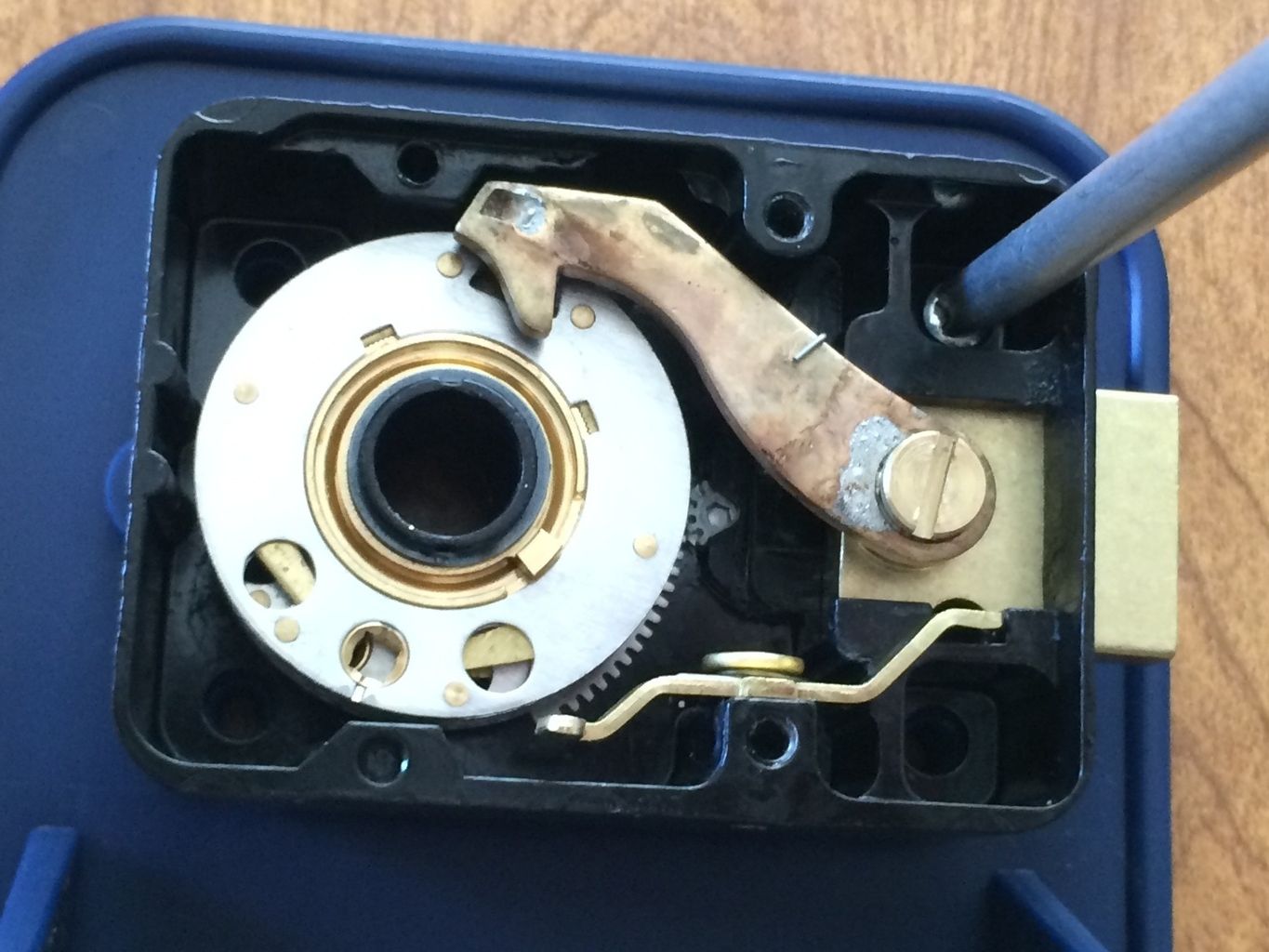
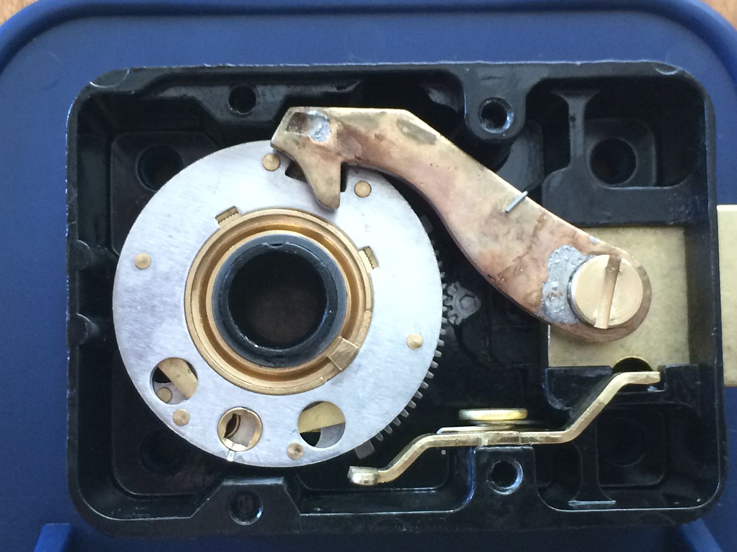
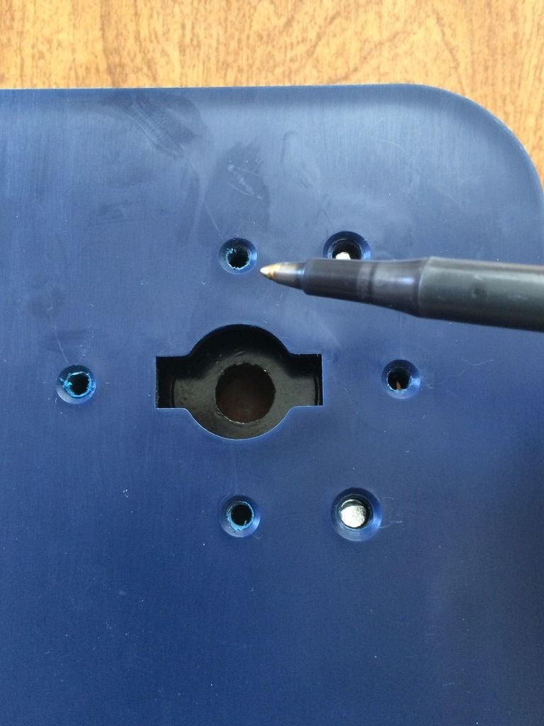
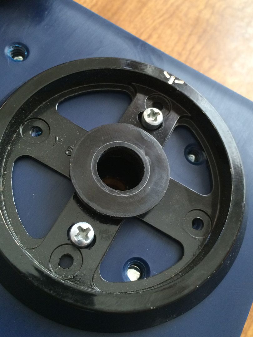
Flip the lock mount over. Now you are looking at the front of the mount/safe door.
There are four screw holes that matter to us on the front. They are to the top, left, bottom and right of the spindle hole. These are for mounting the dial ring.
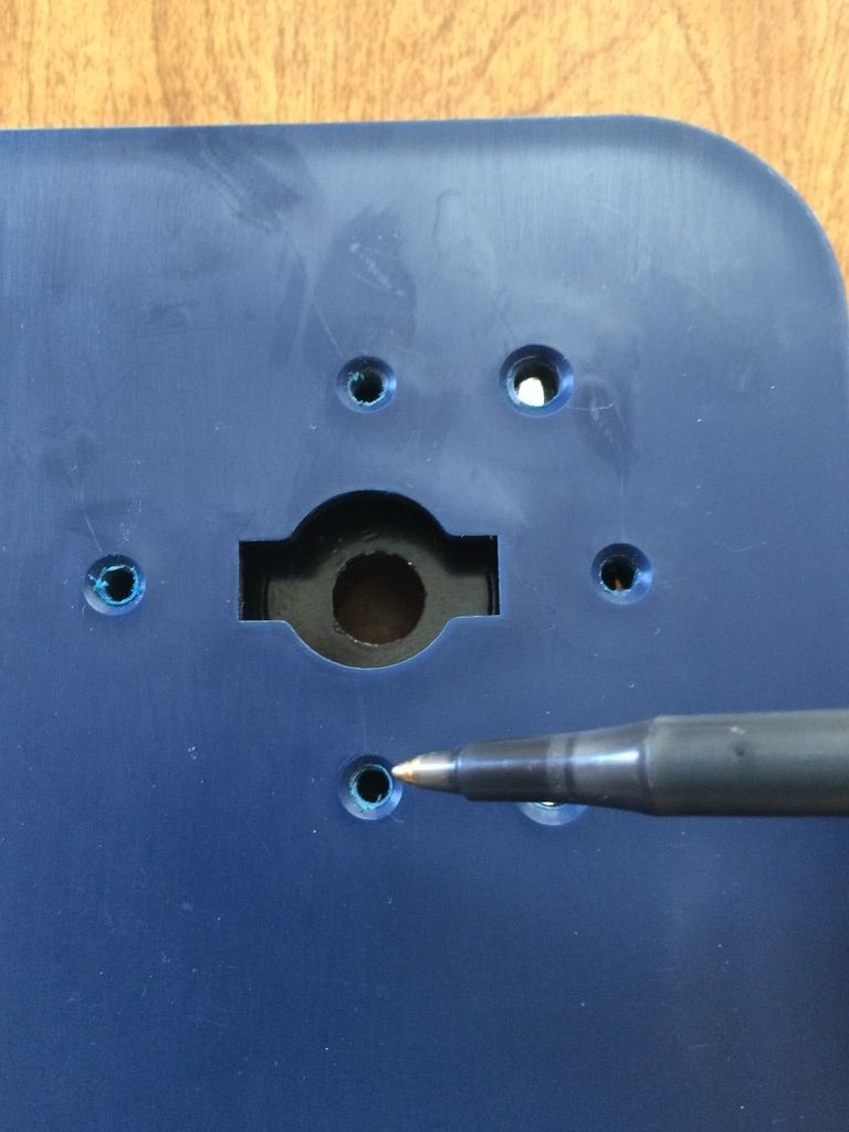
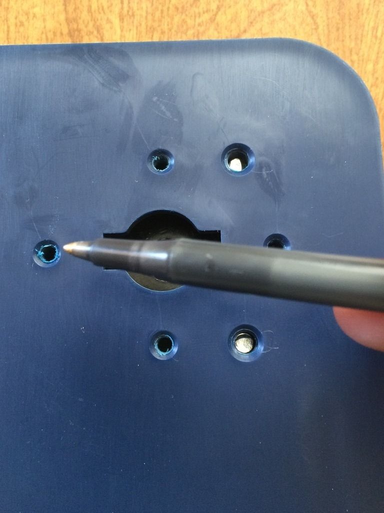
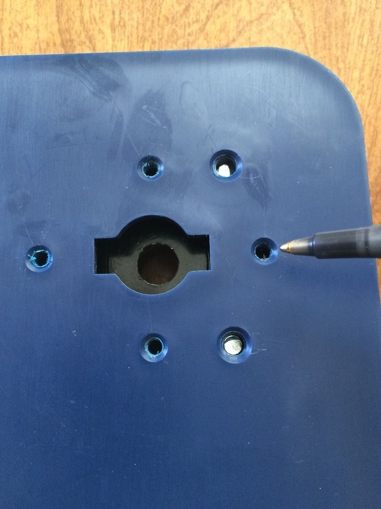
Which ones you use depend on the dial ring you are using. In this case, we will be using the top and bottom ones. Install the two screws, but leave them just loose enough that you can shift the dial ring around with a little effort. You don't want it flopping loose, but not so tight that you can't move it with your fingers.
As you can see, this allows for a fair bit of shifting. This will allow you to align the dial ring to the spindle and lock.
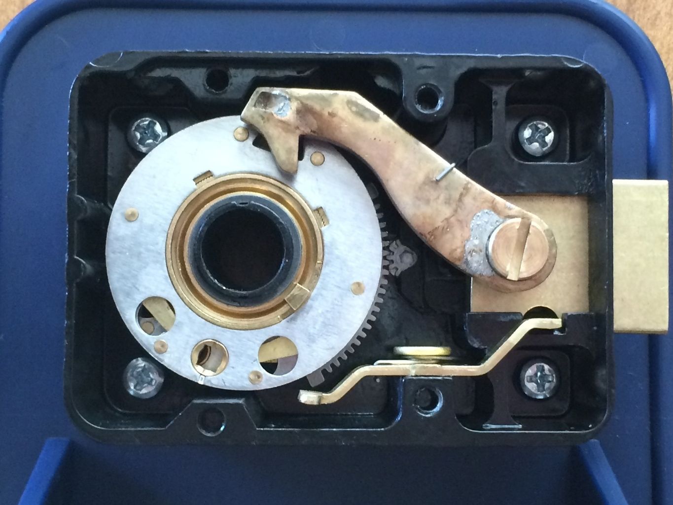
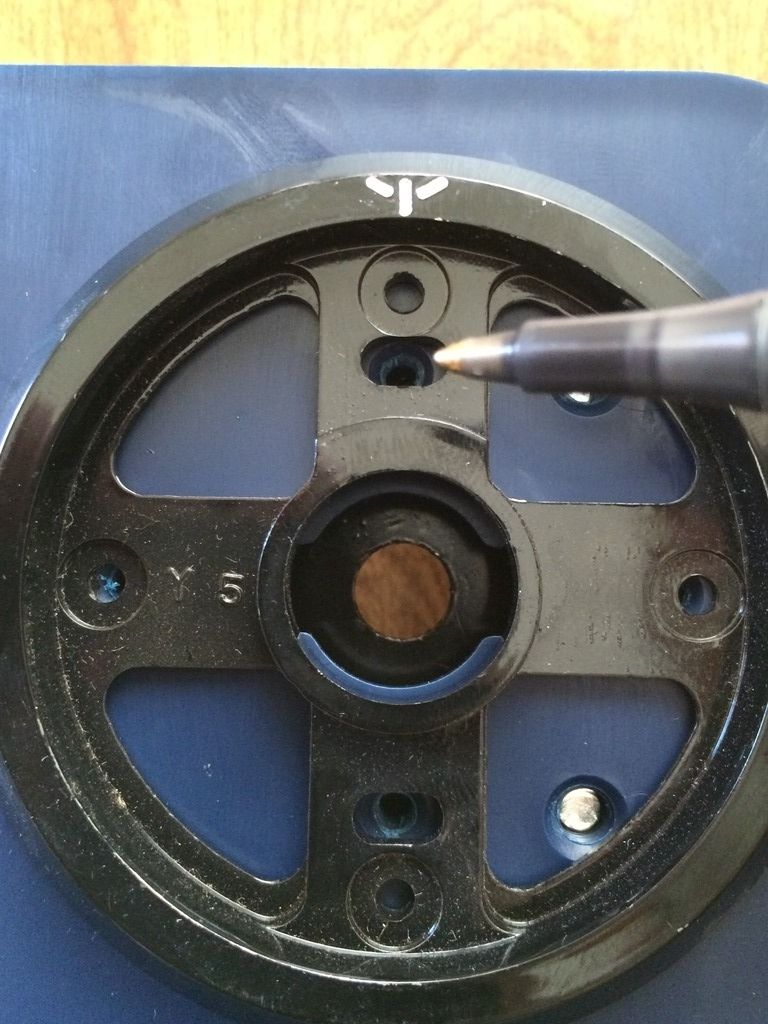
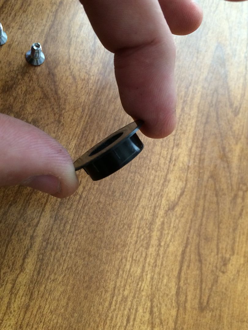
Now install the dial ring bushing.
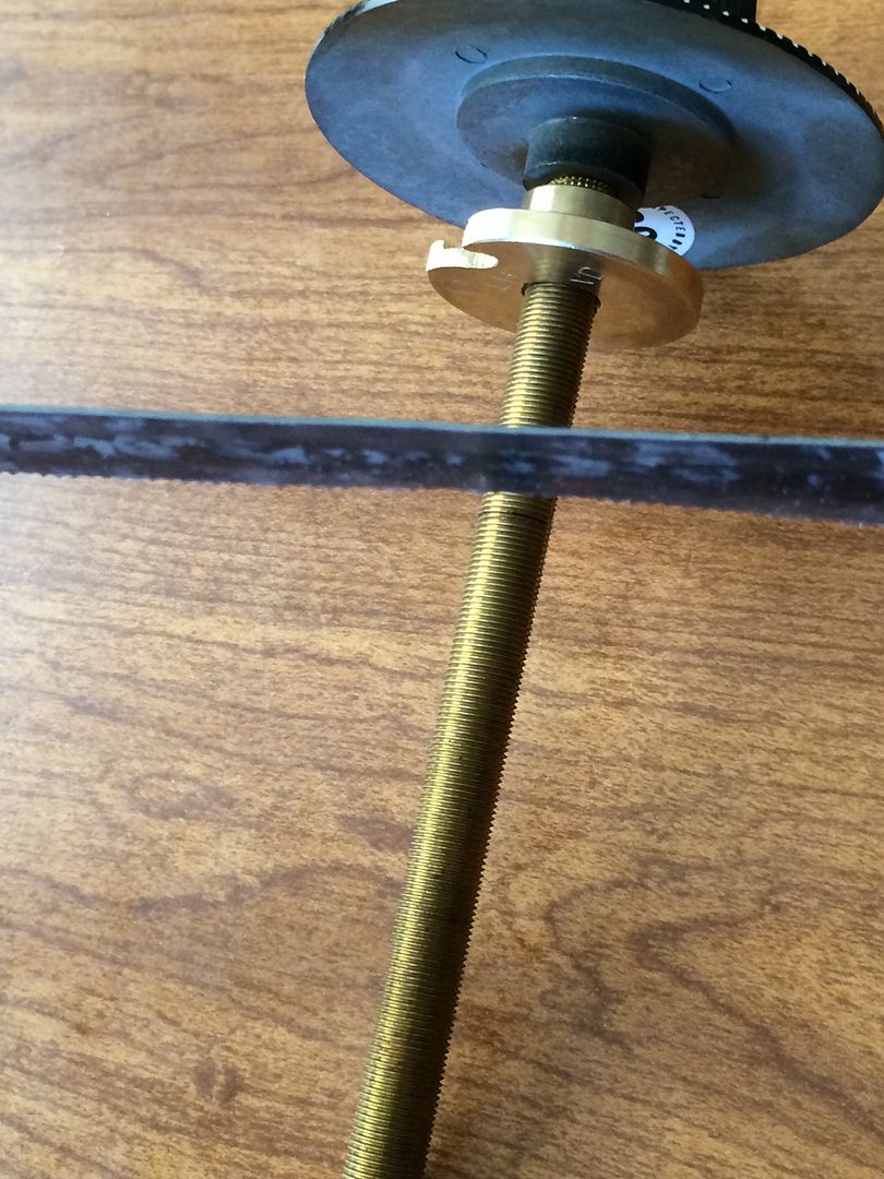
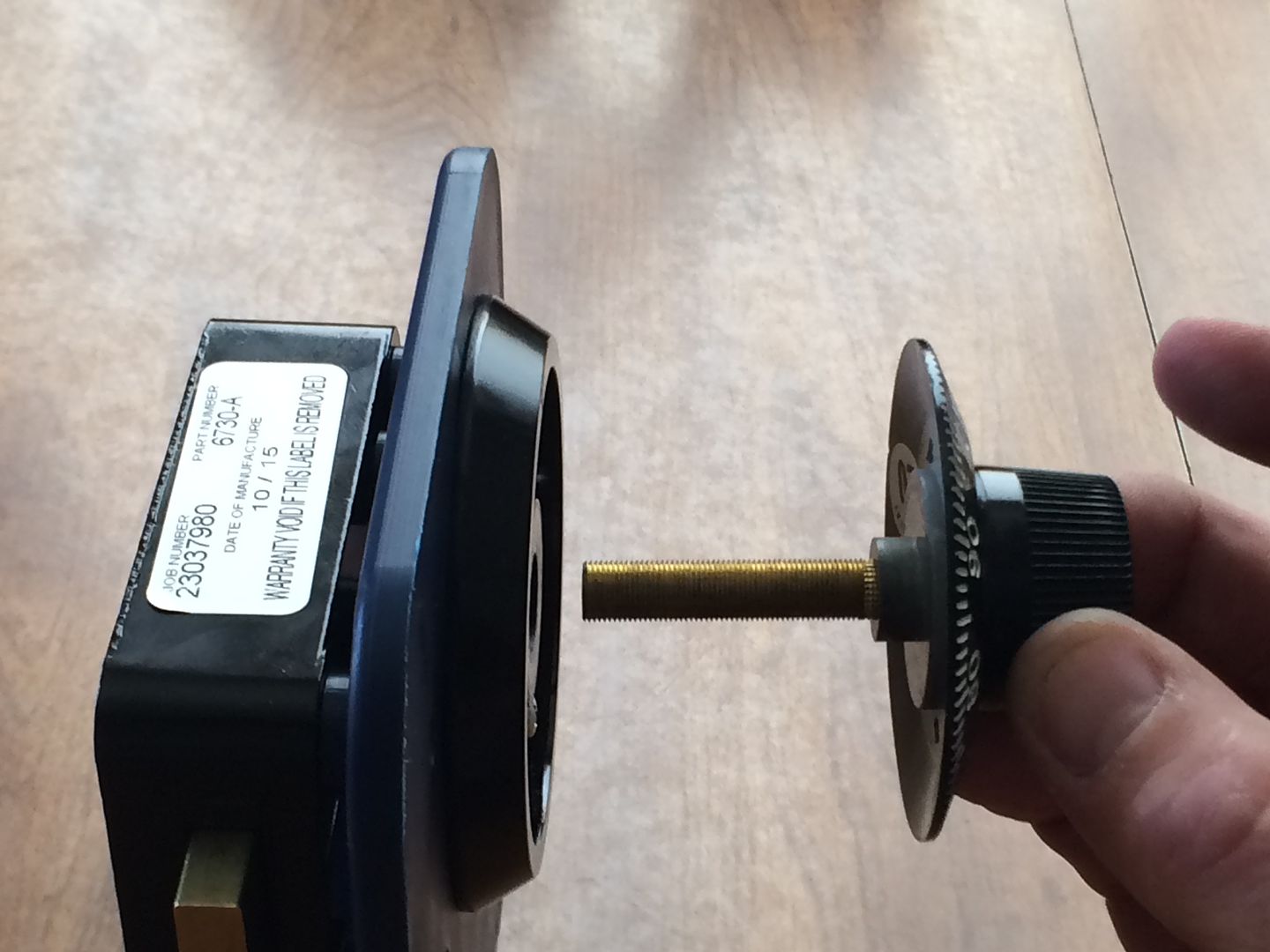
Next comes the dial/spindle.
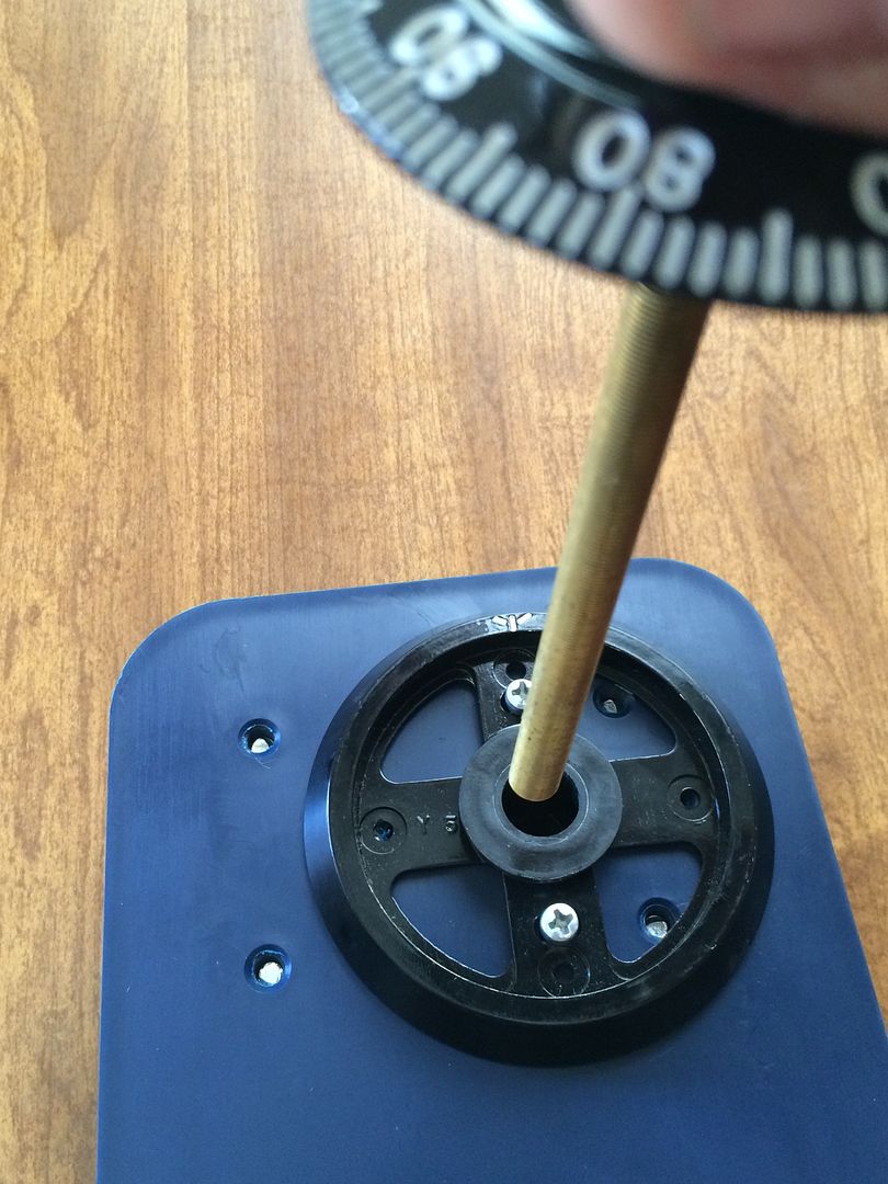
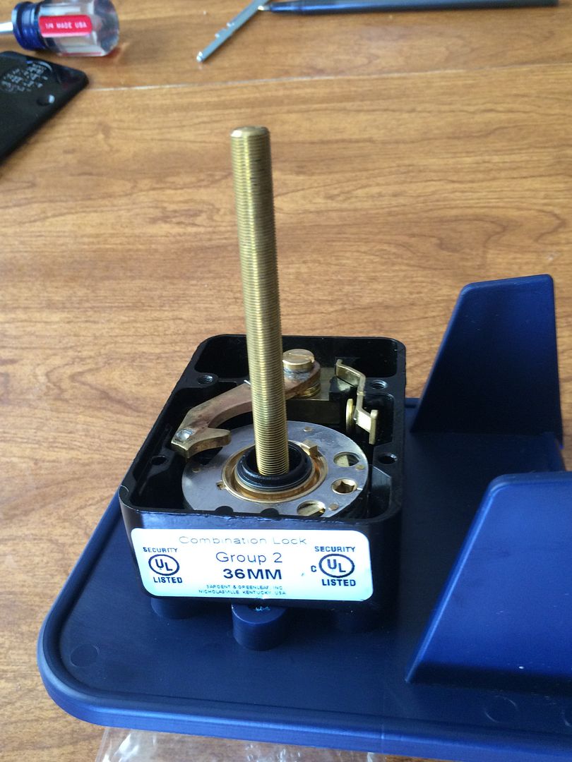
Hmm. Something look a little off to you?
The back cover does not fit because the spindle is too long. Well, good thing there is a simple solution to that problem!
OK, now install the back cover.
Juuuust kidding.
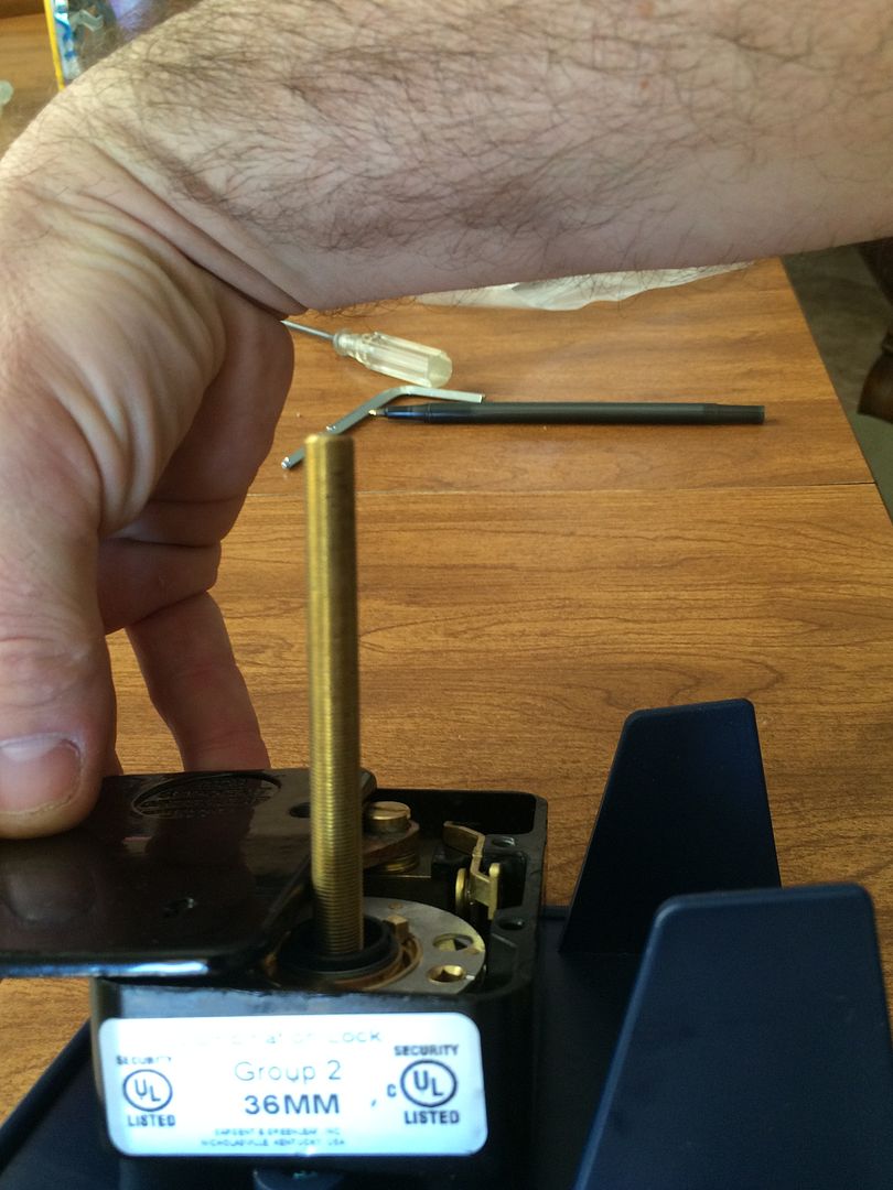
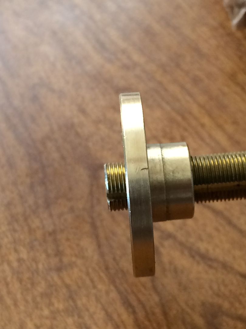
Thread the drive cam onto the spindle until it is all the way down.
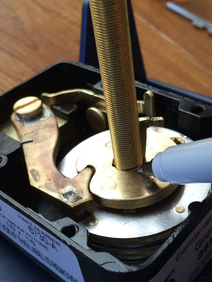
Now use a marker to mark the spindle at the top of the drive cam.
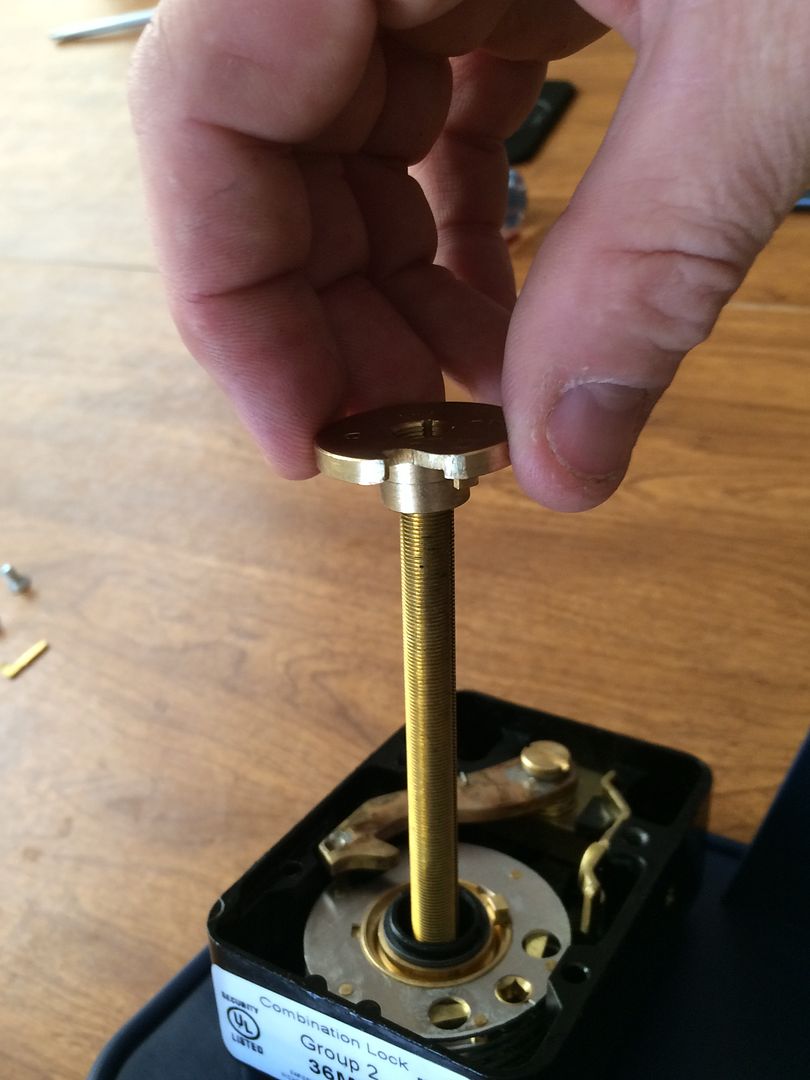
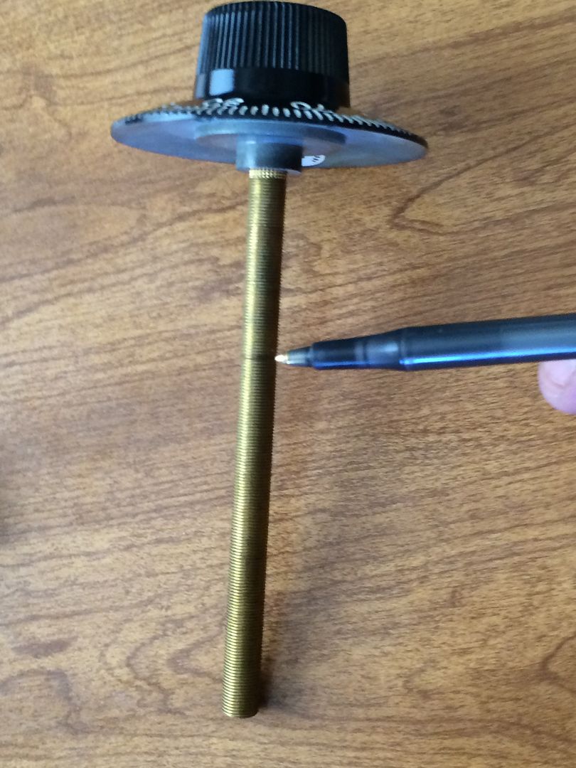
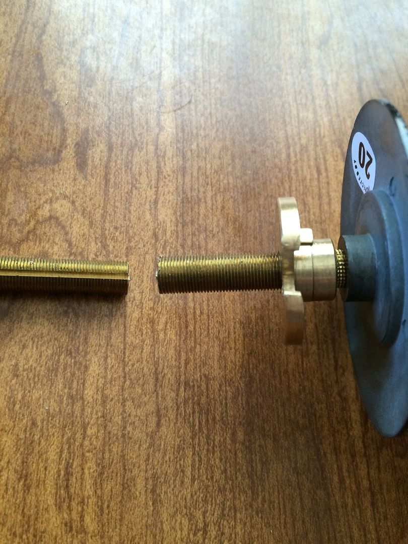
Now remove the drive cam and spindle. Here is the mark. This tells you where to cut the spindle.
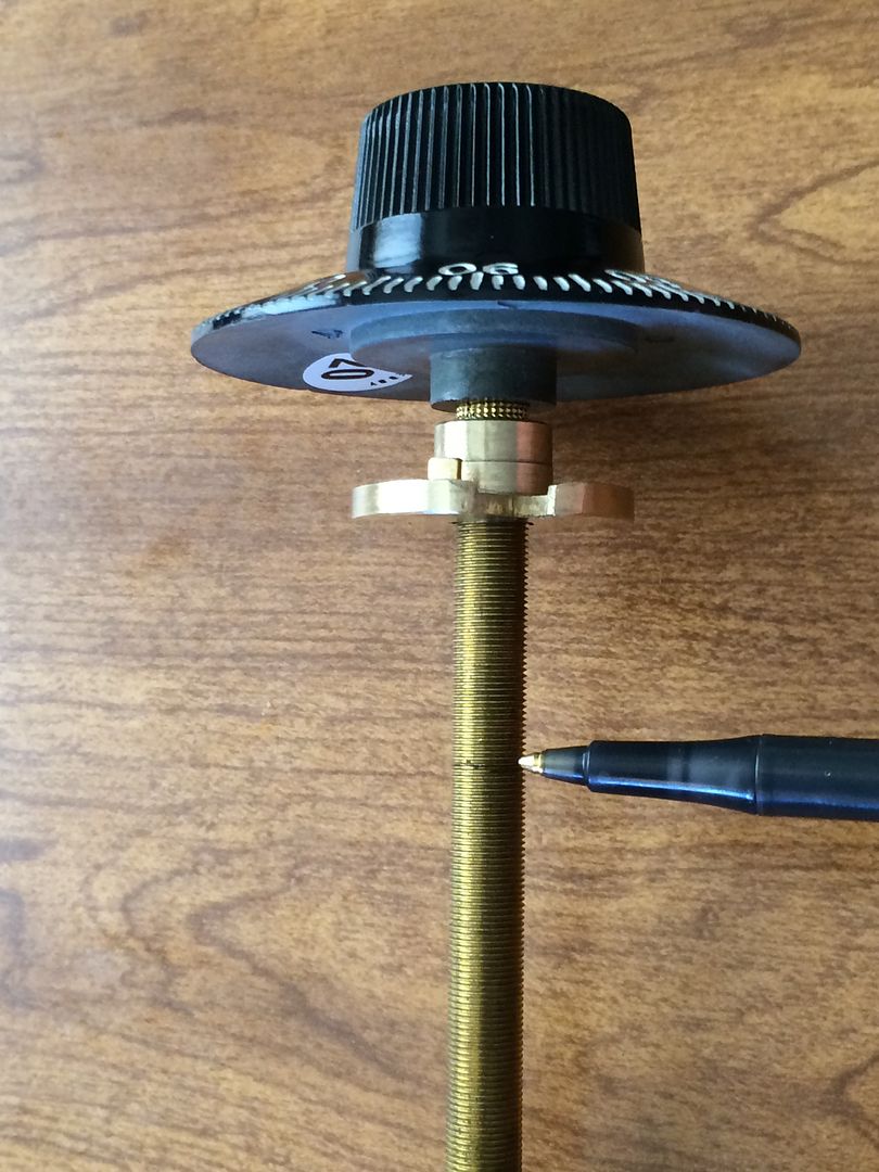
But before you cut, thread the drive cam onto the spindle until it is further down than the mark.
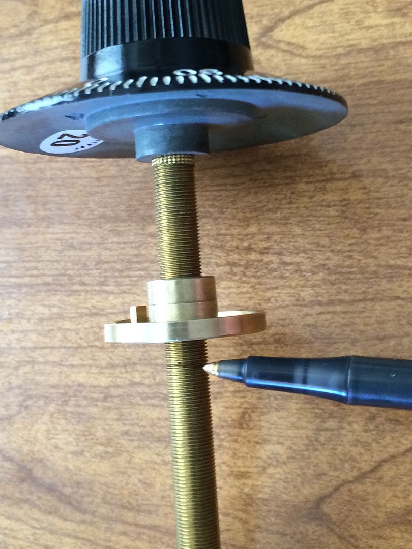
I prefer to thread it all the way down.
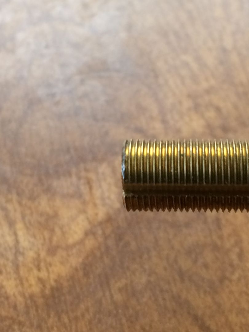
Now cut the spindle with a hacksaw or dremel at the mark.
Clean up the edge a bit with a file.
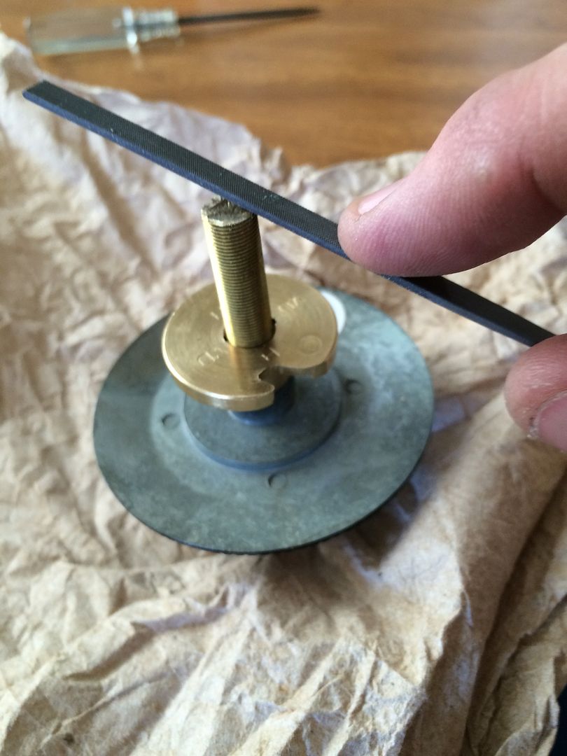
Now if you see the edge, it looks better than when you first cut it. But if you were to try threading the drive cam on at this point, you may end up cross-threading it.
Luckily, you have already threaded the drive cam on before making the cut. You did do that, right?
So you can now simply unthread the drive cam, and it will finish cleaning up the threads on the spindle as the drive cam is removed.
Reinstall the now proper length dial/spindle.
Thread on the drive cam.
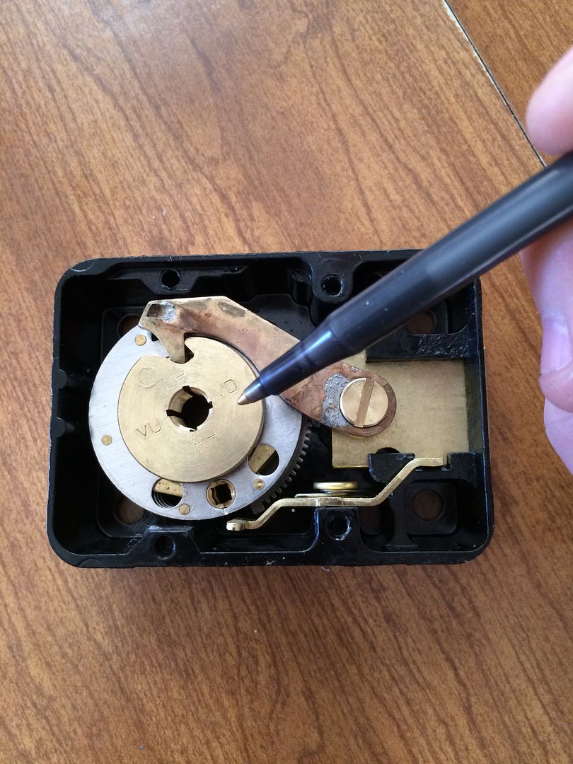
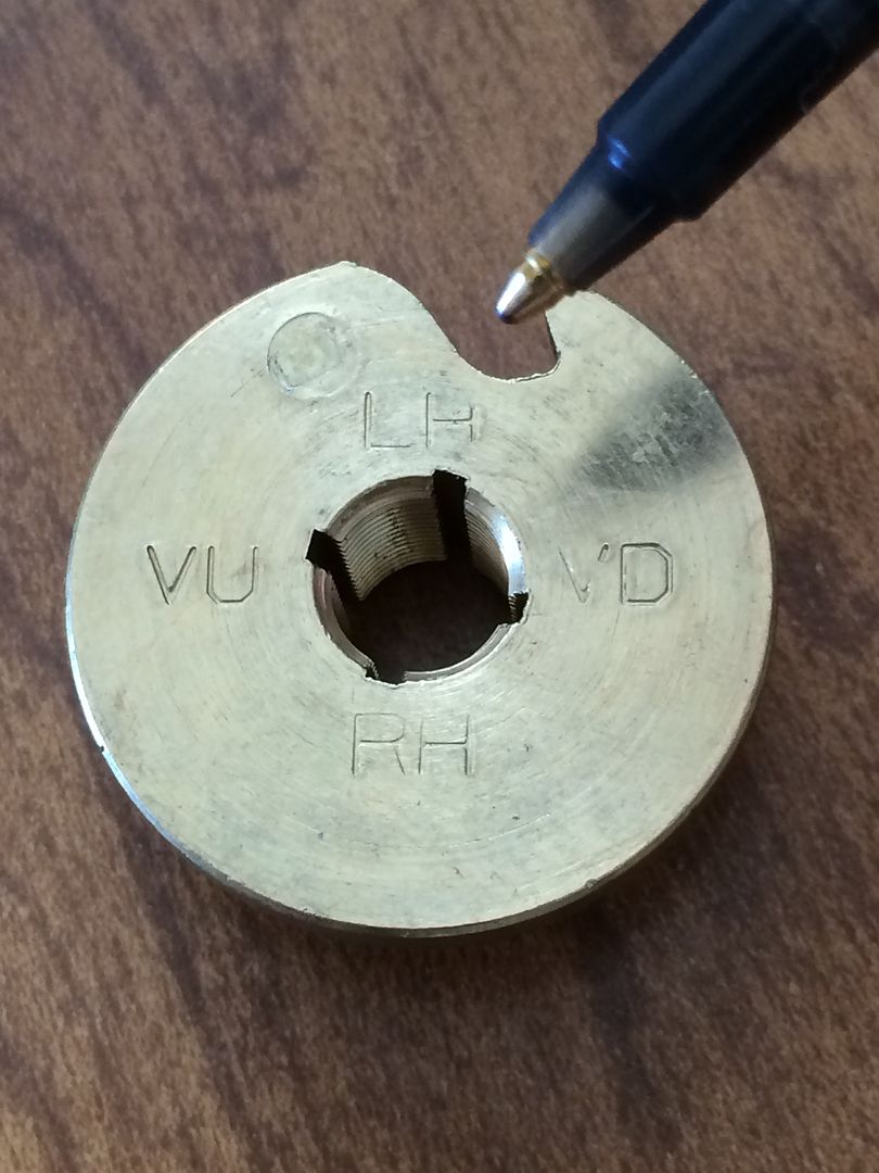
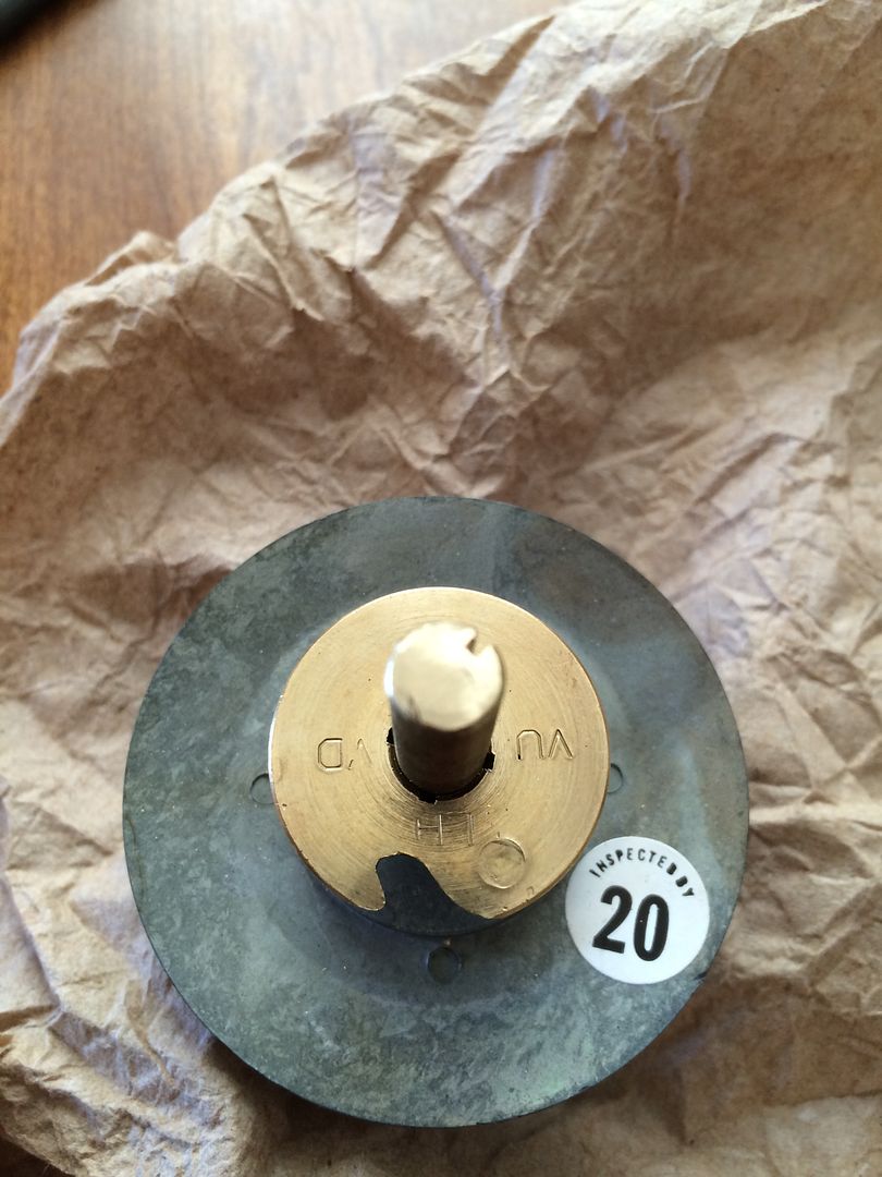
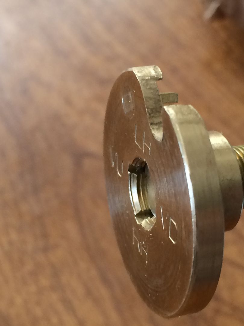
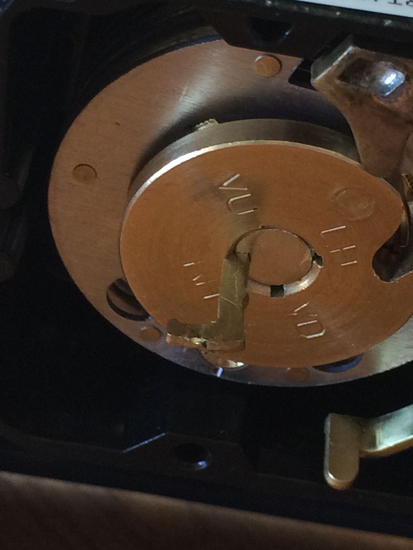
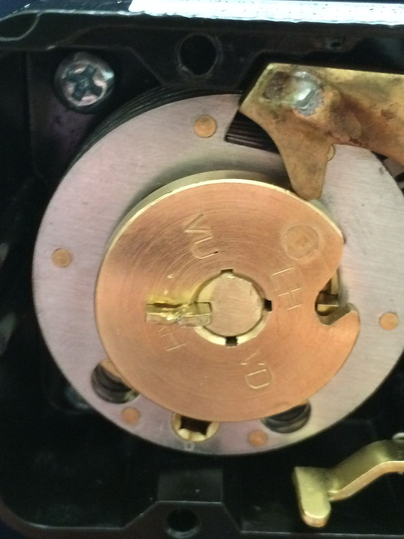
Align the slot in the spindle with the correct orientation slot in the drive cam. There are four orientations in the 6730. These are VU, VD, RH and LH.
You are not aligning the gate (the great big cutout in the outer edge of the drive cam), but the slots on the inside. The orientation you choose is based on the way the bolt of the lock is pointing when viewed from INSIDE the safe.
The letters stand for: Verticle Up (VU), Verticle Down (VD), Right Hand (RH) and Left Hand (LH). This allows the 0 on the dial to be at the top of the dial. If you have the dial splined at the wrong location, the gate will be at (roughly) 25, 50 or 75 instead of 0. The lock will still function, but you will need to adjust your forbidden zone accordingly.
In this case, it is RH. So align the slot in the spindle with the slot at RH.
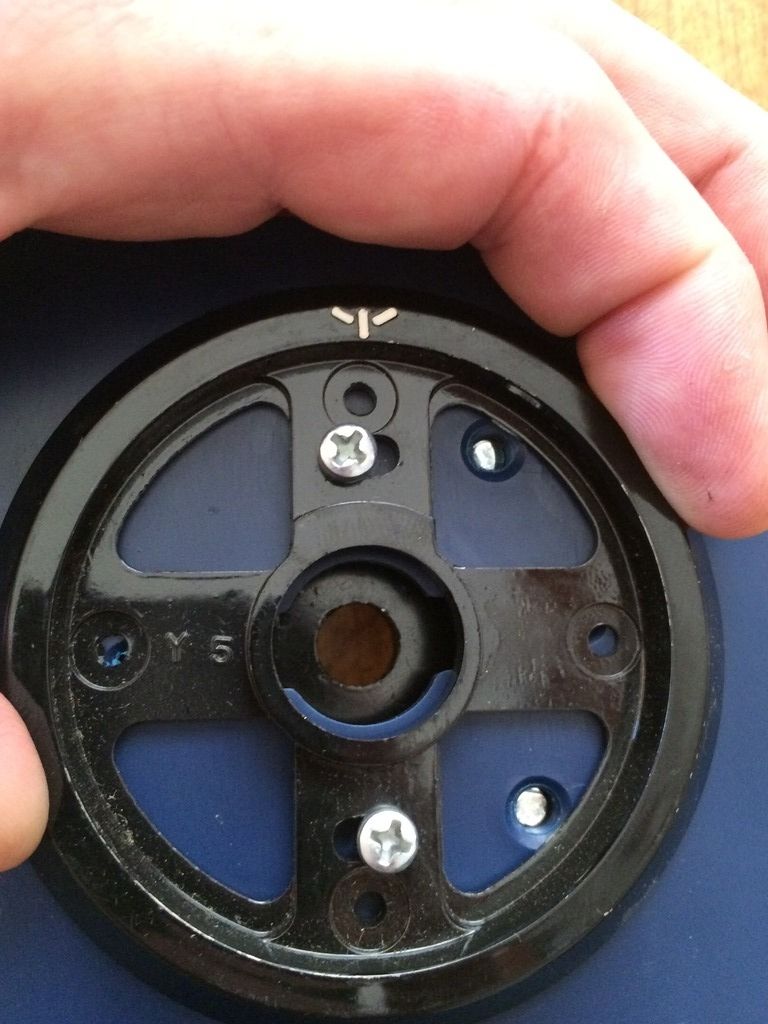
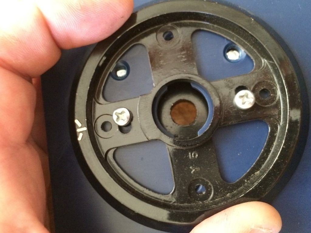
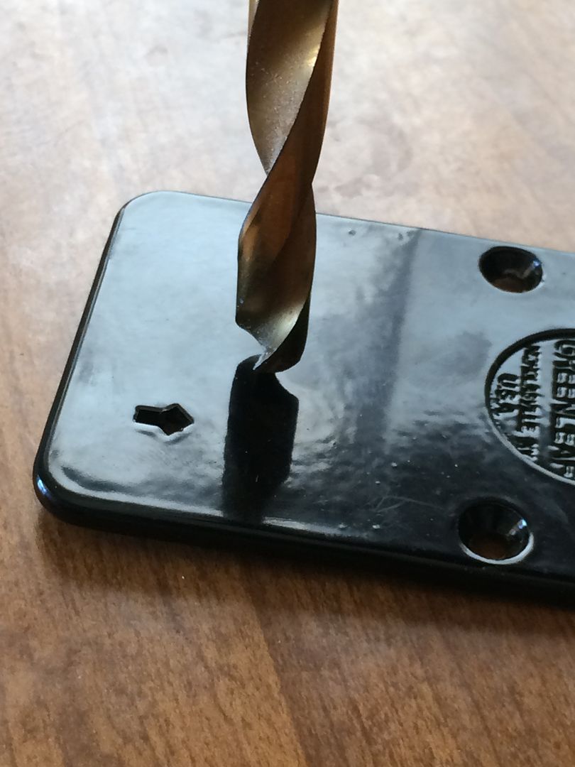
Install your spline key.
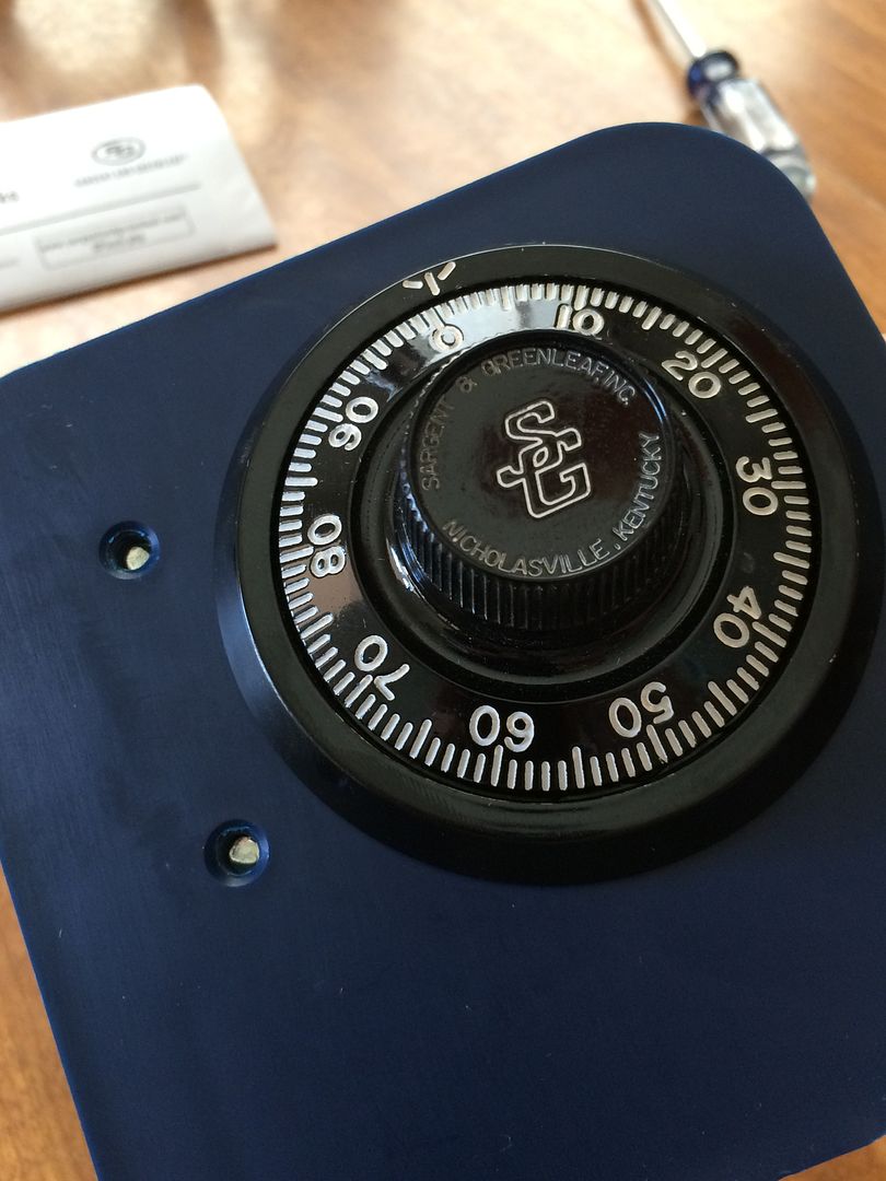
Put the back cover back on, and it is installed!
Set the combination, test it at least three times if it is being installed on a safe to be sure it is working, and you are good to go!
Hope this helps. As always, I am not a safe tech, and anyone should feel free to input additional information or correct any information that I got wrong.
Gordon
Recently mounted an S&G 6730 for another member, and decided to make a post to demonstrate how it is done.
The project requires few parts and fewer tools. There are some tools that would make it a easier to mount on a safe door, such as a dial ring alignment tool. But don't have one.
The tools are a phillips screwdriver, a hacksaw, a small file and a marker. You will need the safe lock, dial, dial ring and dial ring bushing.
And the screws, spline key and a change key (to set the combination).
This is the mount we will be using. This mount already has holes drilled for most modern safe locks and dial rings.
The back of the mount.
Let's get started. Take the two screws off the back of the safe lock.
And remove the back cover.
This is the drive cam.
It lifts right out.
Place the lock body where it will go on the back of the mount (or safe door).
Install the four screws that will hold the lock body in place. They go in the four corners of the lock, and will fully seat against the front of the lock body. (You are looking from the back of the lock when installing).
Flip the lock mount over. Now you are looking at the front of the mount/safe door.
There are four screw holes that matter to us on the front. They are to the top, left, bottom and right of the spindle hole. These are for mounting the dial ring.
Which ones you use depend on the dial ring you are using. In this case, we will be using the top and bottom ones. Install the two screws, but leave them just loose enough that you can shift the dial ring around with a little effort. You don't want it flopping loose, but not so tight that you can't move it with your fingers.
As you can see, this allows for a fair bit of shifting. This will allow you to align the dial ring to the spindle and lock.
Now install the dial ring bushing.
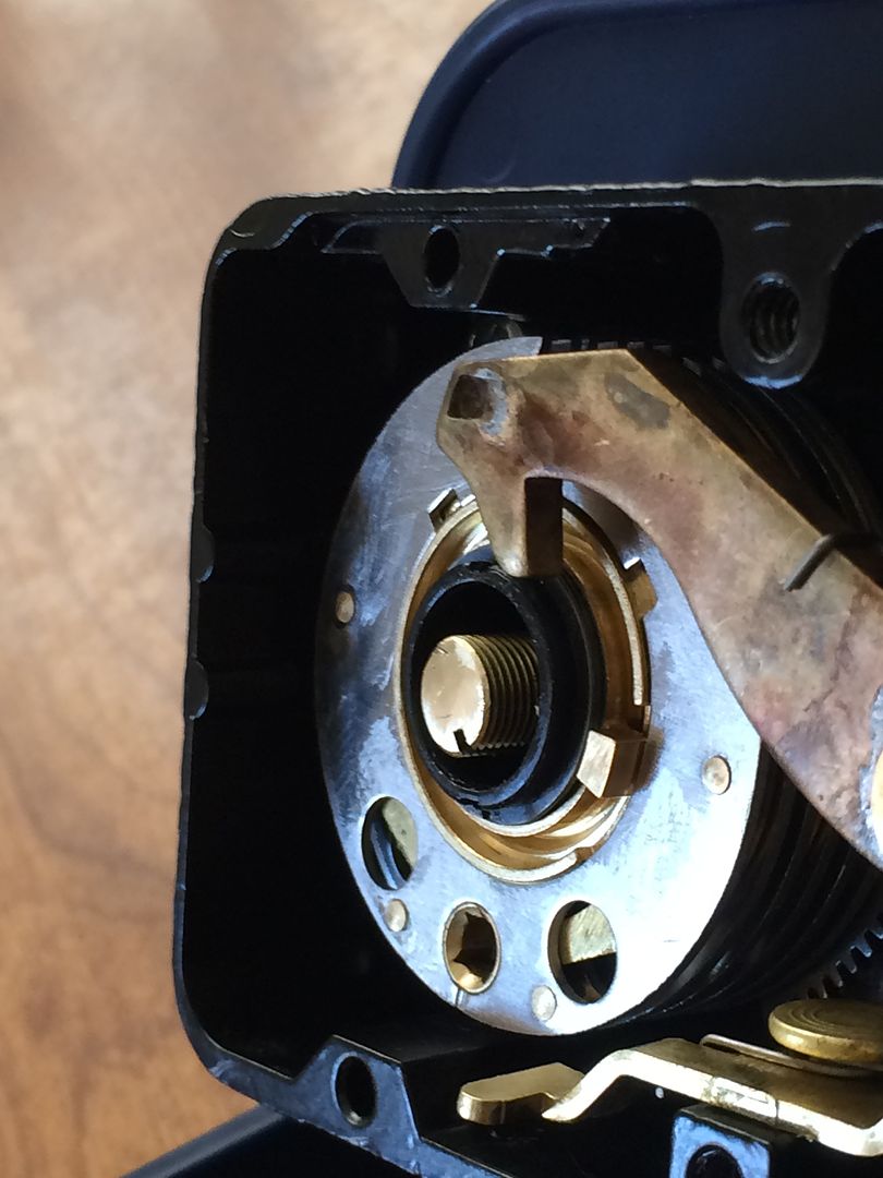
Next comes the dial/spindle.
Hmm. Something look a little off to you?
The back cover does not fit because the spindle is too long. Well, good thing there is a simple solution to that problem!
OK, now install the back cover.
Juuuust kidding.
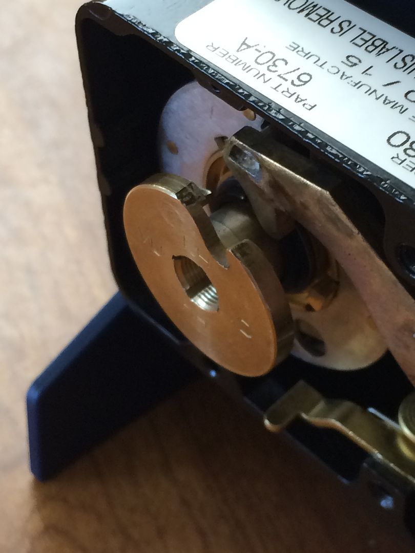
Thread the drive cam onto the spindle until it is all the way down.
Now use a marker to mark the spindle at the top of the drive cam.
Now remove the drive cam and spindle. Here is the mark. This tells you where to cut the spindle.
But before you cut, thread the drive cam onto the spindle until it is further down than the mark.
I prefer to thread it all the way down.
Now cut the spindle with a hacksaw or dremel at the mark.
Clean up the edge a bit with a file.
Now if you see the edge, it looks better than when you first cut it. But if you were to try threading the drive cam on at this point, you may end up cross-threading it.
Luckily, you have already threaded the drive cam on before making the cut. You did do that, right?
So you can now simply unthread the drive cam, and it will finish cleaning up the threads on the spindle as the drive cam is removed.
Reinstall the now proper length dial/spindle.
Thread on the drive cam.
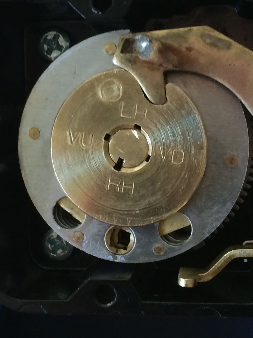
Align the slot in the spindle with the correct orientation slot in the drive cam. There are four orientations in the 6730. These are VU, VD, RH and LH.
You are not aligning the gate (the great big cutout in the outer edge of the drive cam), but the slots on the inside. The orientation you choose is based on the way the bolt of the lock is pointing when viewed from INSIDE the safe.
The letters stand for: Verticle Up (VU), Verticle Down (VD), Right Hand (RH) and Left Hand (LH). This allows the 0 on the dial to be at the top of the dial. If you have the dial splined at the wrong location, the gate will be at (roughly) 25, 50 or 75 instead of 0. The lock will still function, but you will need to adjust your forbidden zone accordingly.
In this case, it is RH. So align the slot in the spindle with the slot at RH.
Install your spline key.
Put the back cover back on, and it is installed!
Set the combination, test it at least three times if it is being installed on a safe to be sure it is working, and you are good to go!
Hope this helps. As always, I am not a safe tech, and anyone should feel free to input additional information or correct any information that I got wrong.
Gordon
Last edited by GWiens2001 on Tue Mar 15, 2016 9:29 pm, edited 1 time in total.
Just when you think you've learned it all, that is when you find you haven't learned anything yet.